

In the field of electronics manufacturing, SMT (Surface Mount Technology) has become a critical process for producing small, lightweight, high-performance electronic devices. This technology involves the soldering of SMT chips and leaded components, as well as the storage and application of solder paste. This article will take an in-depth look at these key areas.
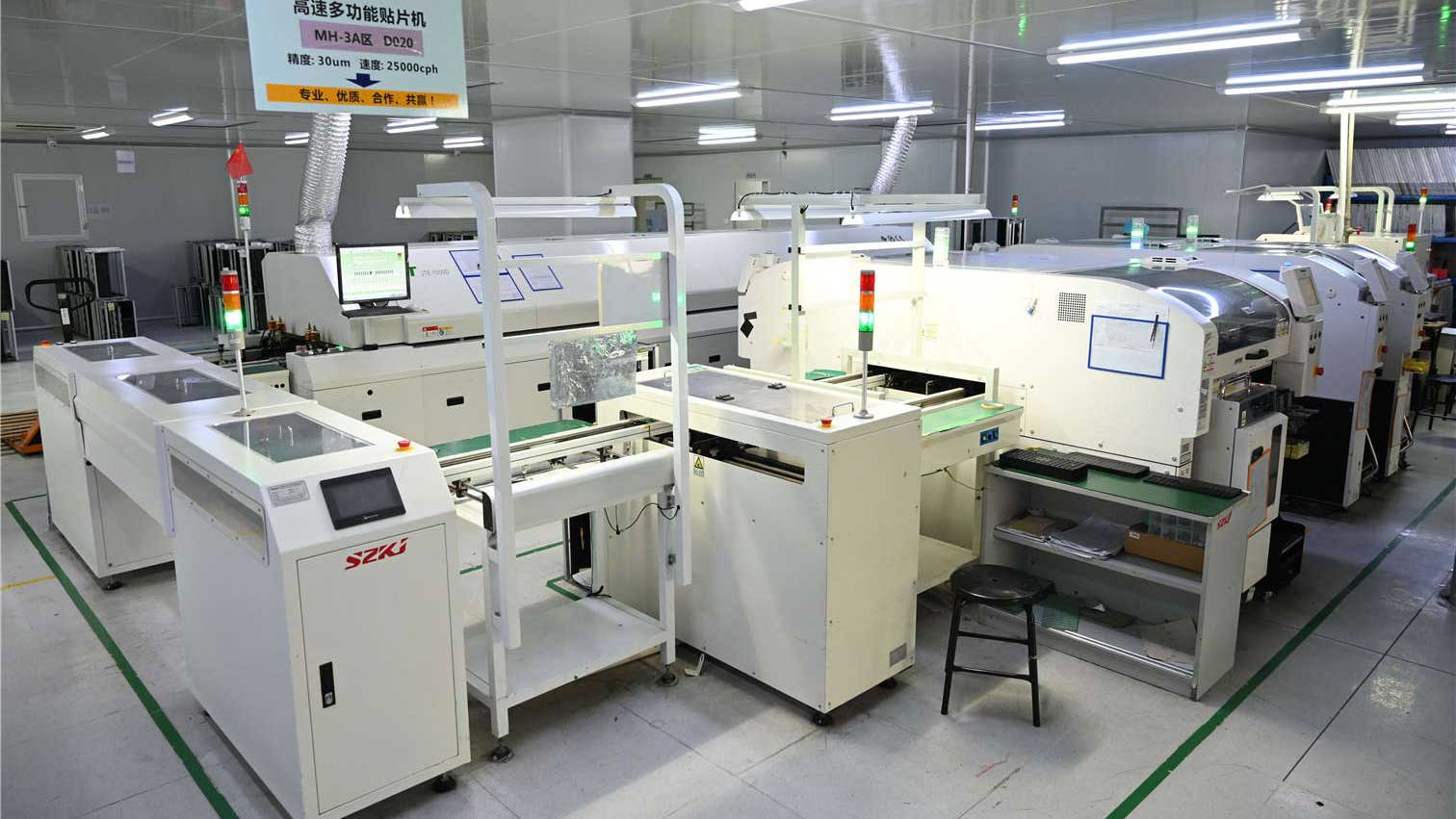
Advanced: How to Choose the Right Temperature and Tools for Manual Soldering
When manually soldering SMT components, the most common source of problems isn't the technique itself, but ratherTemperature does not match the tool. If you choose the wrong parameters, even the best technique won't be able to make up for it:
| Object | Soldering Iron Temperature | Soldering Iron Tip | Key Points |
|---|---|---|---|
| Small-Size Resistors and Capacitors (0201–0805) | 300–330 °C | Pointed tip or blade tip | Keep the duration short to prevent the device from cracking due to heat. |
| SOP / QFP Leads | 320–350 °C | Cutting head | When performing drag soldering, make sure the leads are properly tinned. |
| QFN / DFN Bottom Pads | Preheating Station Required | Cutting Head + Hot Air | The bottom pads rely on reflow; do not apply excessive pressure. |
| BGA | Hot-air or rework station | — | A temperature curve is required; single-point heating is not acceptable. |
| Large Pad and Ground Plane | 350 °C or higher, or preheat | High-Power Soldering Iron | Large copper surfaces dissipate heat quickly, so additional heat must be supplied. |
- Lead-containing and lead-free versions have different operating temperatures.: Lead-free solder has a higher melting point, typically 20–30 °C higher;
- Keep contact time between 2 and 3 seconds: Prolonged exposure can damage the components and pads;
- Tin the larger pads first.: It's much easier to apply a thin layer of solder to the pad first, then position the component, rather than doing it the other way around.
- Use the appropriate amount of flux.: Too little results in poor wetting; too much leads to excessive residue and splashing;
- First, secure the two diagonal legs.: For multi-pin devices, solder the pins diagonally across first, then solder the remaining pins;
- Clean in the direction of the pins.: Avoid pushing the flux into the gaps between the solder joints.
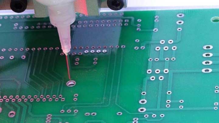
For information on dispensing and soldering technologies, seeDispensing and Soldering Technology for SMT Dispensers; For practical welding tips, see12 Tips for SMT Soldering。
SMT Assembly and Lead Modules
SMT AssemblySMT components play a crucial role in electronics manufacturing. Compared to traditional leaded components, SMT components are easier to solder, which makes circuit board manufacturing more efficient. In addition, SMT components improve circuit stability and reliability, which is crucial for increasing production yield. This is because SMT components lack leads, thereby reducing the generation of stray electric and magnetic fields, particularly in high-frequency analog circuits and high-speed digital circuits.
Soldering SMT Wafer Assemblies
Soldering SMT components onto a circuit board is a critical process step. First, place the SMT components onto the pads. Next, apply an appropriate amount of solder paste to the contact points between the component leads and the pads. It is important to avoid applying too much solder paste to prevent short circuits. Next, use a 20W internal-heating soldering iron set to a temperature of approximately 220–230°C to heat the contact points between the pads and the SMT components. Once the solder paste has melted, remove the soldering iron and wait for the solder to solidify, completing the soldering process. To ensure the quality of the solder joint, use tweezers to hold the soldered SMT component and check for any looseness. If there is no looseness, the solder joint is very secure.
Advanced: How to Choose Among the Three Solder Paste Application Methods
| Method | Principle | Accuracy | Efficiency | Applicable |
|---|---|---|---|---|
| Steel Plate Printing | The squeegee transfers the solder paste through the openings in the steel mesh. | 高 | 高 | High-volume, fine-pitch |
| Dispensing and Coating | Needle Extrusion for Metered Coating | 中 | 低 | Small-batch, localized solder reflow |
| Point-to-Point Transmission | Transfer the solder paste to the leads or pads | 低 | 低 | Wide spacing, few components |
Steel plate printing is the mainstream method for mass production, and its key parameters areWire Mesh Thickness, Aperture Size, and Aperture Shape. These three factors collectively determine the volume of the solder paste, and the volume of the solder paste directly determines the quality of the solder joints: too little results in cold joints, while too much results in solder bridges.
- The area ratio must be sufficient: If the ratio of the opening area to the wall area is too small, it can lead to poor demolding and solder paste residue;
- For fine pitch, use a via with a reduced diameter.: If the spacing is too small, reduce the hole size appropriately to minimize the risk of solder bridging;
- Stepped Steel Mesh: When there are significant differences in component sizes on a single board, use localized thinning to accommodate varying solder requirements.
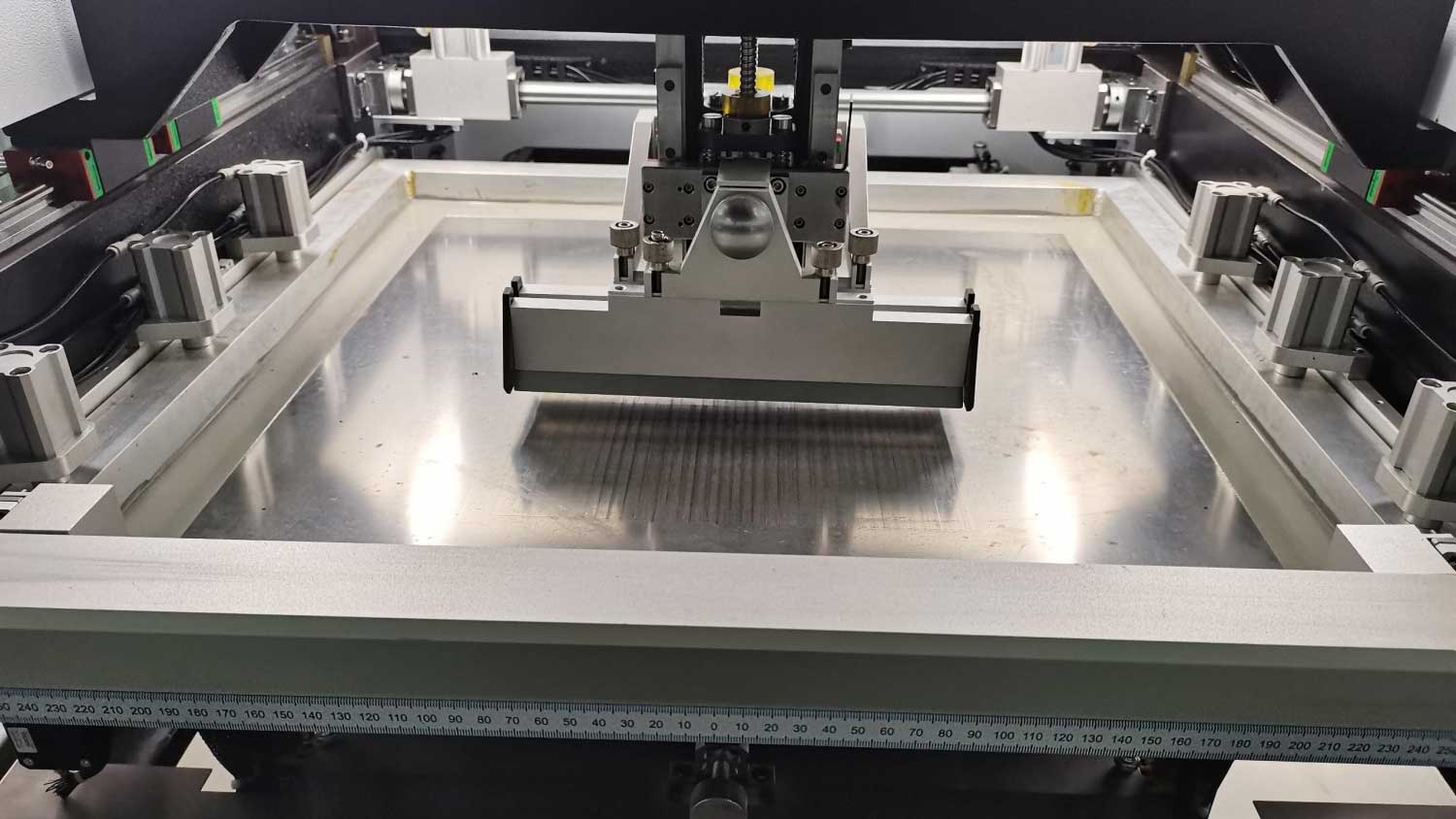
For the solder paste printing process, seeSMT Solder Paste Printing Process Flow; For the causes of solder paste short circuits, seeAn In-Depth Analysis of the Causes of Solder Paste Short Circuits。
SMT Lead Assembly Soldering Methods
Unlike SMT surface-mount soldering, SMT lead assembly soldering requires more steps and meticulous handling. When soldering leads, apply solder to the soldering iron tip and apply flux to all leads to keep them wet. Next, gently touch the tip of the soldering iron to the end of each pin until you see solder flowing into the pin. Throughout the soldering process, ensure that the soldering iron tip remains parallel to the pins to prevent excessive soldering and pin overlap.
After soldering all the pins, dip them in flux to clean the solder. Remove excess solder where necessary to eliminate any potential short circuits and solder overlap. Finally, use tweezers to check for cold solder joints. After completing the inspection, remove the flux from the circuit board. You can use a stiff-bristled brush dipped in alcohol to carefully wipe along the direction of the pins until the flux is completely gone.
Advanced: Six Key Points for Solder Paste Management
Solder paste is the most “delicate” material in SMT; it is sensitive to temperature, humidity, and time. Defects caused by improper handling often occur in batches, resulting in high costs:
- Refrigerated storage: It is typically required to be stored at low temperatures to slow down the reaction between the flux and the alloy powder;
- Open after it has warmed up: Be sure to wait until the temperature has equilibrated with the ambient temperature before opening the lid; otherwise, moisture in the air will condense on the surface of the cold solder paste;
- Record the time it takes to warm up: It is not appropriate to let the food warm up too little or for too long; the duration should be determined based on the size of the container and the storage temperature;
- Stir, not knead: Before use, stir according to specifications to ensure the alloy powder and flux are evenly mixed, and to prevent the introduction of air bubbles;
- Limit the Duration of Use: Once opened, there is a specific time limit for use on the production line; after this time has elapsed, the product must be discarded;
- Do not mix old and new items: Do not mix solder paste from different batches or in different states, as this can cause unstable printing performance.
Of these, Article 2 is the one most likely to be overlooked.Condensation is the number one cause of solder paste scrap.: If you open the package immediately after removing it from the refrigerator, condensation will mix with the solder paste, causing solder splatter, solder balls, and porosity—and these issues often don’t become apparent until after reflow.
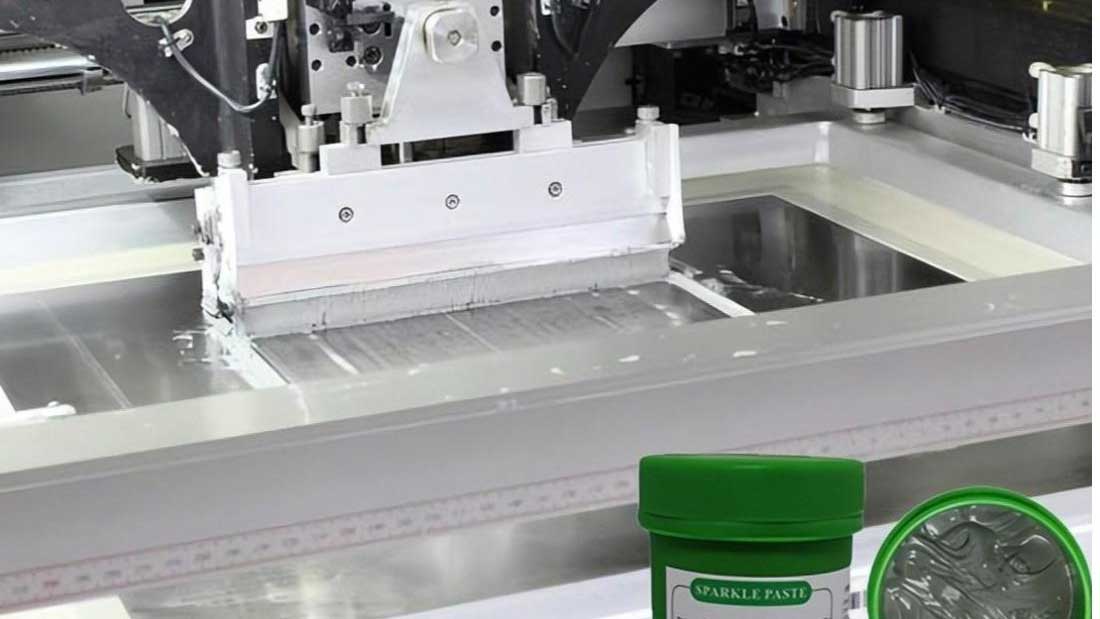
For the basics of solder paste, seeAn Introduction to Solder Paste Used in SMT Assembly; For the difference between the solder mask layer and the solder paste layer, seeWhat Are Solder Mask Layers and Solder Paste Layers?。
Use and Storage of Solder Paste on PCBs
Solder paste plays a critical role in PCB manufacturing. It is used to melt the chip adhesive, firmly bonding surface-mount components to the PCB. The quality and application method of solder paste have a significant impact on the power efficiency of the circuit board. The following is key information regarding the use and storage of solder paste:
Solder Paste Coating Technology
The most commonly used solder paste application techniques among PCB manufacturers include steel plate printing and screen printing. Steel plate printing is based on the concept of screen printing, but compared to screen printing, it allows for more precise control over the amount of solder paste applied, making it suitable for the assembly of fine-pitch components. In steel plate printing, the metal aperture pattern on a thin metal plate matches the pads where solder paste is to be applied. Before printing, the steel plate is aligned with the circuit board, and then a squeegee is used to apply solder paste across the entire steel plate, transferring the solder paste through the openings in the steel plate to the desired areas. Finally, the circuit board is separated from the steel plate, leaving the solder paste on the corresponding pads.
Dispensing and Coating Technology
Dispensing technology involves using a needle to extrude solder paste for precise, metered application at specific locations. This technique is suitable for applications requiring solder paste to be applied at specific locations, such as in the manufacture of fine-pitch components. Dispensing is generally slower than screen printing, so it is typically used for small-volume production or tasks that require greater precision.
Point-to-Point Transmission Method
For small components with wide spacing, the point-to-point transfer method is a good choice. This method involves transferring solder paste to the desired location on the leads. It can be used to transfer solder paste between different pads. This technique requires applying solder paste to the leads and then aligning the leads with the pads. This method is typically used in the manufacture of components that require wider spacing.
Storage of Solder Paste
Solder paste is highly sensitive to heat, air, and humidity. Therefore, special precautions must be taken when storing solder paste to ensure its quality remains unaffected. Here are some important recommendations for storing solder paste:
- Solder paste should be stored in a refrigerated environment to prevent exposure to high temperatures.
- Before opening the package and before exposing the solder paste to air, the temperature of the solder paste should be allowed to equilibrate with the ambient temperature to prevent condensation.
- The reheating time for solder paste depends on the size of the container and the storage temperature.
Advanced: Troubleshooting Sequence for Common Welding Defects
| Defects | Prime Suspect | Troubleshooting Steps |
|---|---|---|
| Lead-to-Lead Connection | Excessive solder paste, stencil apertures too large | Measure solder paste thickness and check via dimensions |
| Poor Solder Joints Due to Insufficient Solder | Insufficient solder paste, oxidized pads | Inspect print quality and pad solderability |
| Solder balls | Solder paste absorbs moisture; preheating is too rapid | Check the temperature history and the reflux curve |
| Erecting a Monument | Uneven heating at both ends; asymmetrical pads | Check the pad design and preheat ramp |
| Pores | Solder paste absorbs moisture; flux does not evaporate properly | Check Storage and Curves |
- Look at the solder paste first, then the equipment: Most defects stem from the condition of the solder paste and the stencil, not the placement machine;
- First, check the backflow curve.: Curve drift is a common cause of batch defects and is often overlooked;
- Retain samples by batch: Keep records of the printing and reflow processes for each batch so that issues can be quickly identified when they arise.
For key points on SMT machine programming, seeOnline Programming for SMT Placement Machines; For SMT manufacturing requirements, seeWhat information do customers need to provide before SMT assembly?。
Summary
SMT soldering and the use of solder paste are critical steps in the electronics manufacturing process, as they directly impact the performance and reliability of electronic devices. By mastering these techniques, manufacturers can improve the quality of their products and meet growing market demand.
If you have any questions about SMT soldering, the use of solder paste, or other issues related to electronics manufacturing, please feel free to contact us at any time. We will be happy to provide you with support and answer your questions.
Frequently Asked Questions
1. Is a heat gun absolutely necessary when manually soldering SMT components?
Not necessarily. Components with two pins and those adjacent to other components can be handled with just a soldering iron; only components like BGAs and QFNs, which have pads on the bottom, require a hot-air gun or a rework station. The advantage of a hot-air gun is that it heats the entire component, preventing localized overheating, but it has a greater thermal impact on surrounding components, so proper shielding is necessary.
2. How long after taking the solder paste out of the refrigerator can it be used?
Wait until the container has reached equilibrium with the ambient temperature before opening it. The exact time required depends on the container’s size and storage temperature, but it typically takes several hours. The indicator that the container is ready is when condensation no longer forms on its outer surface. Opening the container before it has reached equilibrium is the most common cause of solder paste failure.
3. How do you choose the thickness of the wire mesh?
Determine the thickness based on the solder requirements of the component with the smallest pitch on the board. The finer the pitch, the thinner the stencil should be; otherwise, excess solder paste may cause solder bridges. However, if the stencil is too thin, larger components may not receive sufficient solder. When there is a significant size difference between components, consider using a stepped stencil with varying thicknesses in different areas.
4. How can you determine if a weld is acceptable after welding?
Visually, the surface should appear smooth, glossy, and concave, with the solder spread evenly and free of cracks or pinholes. Functional integrity must be verified using AOI or X-ray inspection; hidden solder joints, such as those on BGAs, must be inspected using X-rays. If necessary, a sample should be sectioned to examine the internal quality of the solder joints.
5. Can leaded components and SMT components be reflow-soldered together?
In some cases, yes. High-temperature-resistant leaded components can be reflow-soldered along with SMT components, but non-high-temperature-resistant components—such as connectors and electrolytic capacitors—must be added later, typically through selective soldering or manual rework. When scheduling mixed-assembly processes, the sequence must be planned in advance.
6. Should flux residue be cleaned off?
This depends on the type of flux and the product requirements. No-clean flux can generally be left on the board, but for high-reliability products or applications requiring conformal coating or dispensing, cleaning is typically required, as residues can affect subsequent processes and long-term reliability.
7. Why are defects more likely to occur in lead-free soldering?
Lead-free solder has a high melting point and relatively poor wettability, requiring higher soldering temperatures and more precise temperature profiles; its process window is narrower than that of leaded solder. In addition, high temperatures place greater thermal stress on components, PCBs, and fixtures; therefore, lead-free processes place significantly higher demands on process control.
8. How long can solder paste be used after it has been opened?
There are specific time limits for the use of each production line, typically measured in hours, depending on the solder paste type and environmental conditions. Once this time limit is exceeded, the solder paste’s printing performance deteriorates, which can lead to issues such as insufficient solder and poor formation. There is also a limit to the number of times unused solder paste on the stencil can be reused.
9. Why do solder balls form during soldering?
There are three main causes: moisture absorption by the solder paste, flux splatter caused by excessive preheating rates, and solder paste overflowing the pads due to printing misalignment. The corresponding solutions are to standardize the preheating process, slow down the preheating rate, and correct the printing alignment.
10. How do you maintain a soldering iron tip?
Apply solder to the tip after each use to prevent dry heating; regularly remove oxidation with a specialized cleaner. Do not scrape the tip with hard objects such as files, as this may damage the plating. Oxidation of the soldering iron tip can impair heat transfer, resulting in the tip failing to reach the desired temperature and dark solder joints—which are hidden causes of cold solder joints.
Related Recommendations:Stability and Reliability of Multilayer PCBs · An Introduction to Solder Paste Used in SMT Assembly
