

Flex-Rigid Boards Enabling Circuit Connections in Three-Dimensional Space
Combine device mounting in the rigid regions with spatial connections in the flexible regions. Evaluate manufacturable rigid-flex solutions based on assembly configurations, stacking, and bending conditions.

Rigid-Flex Printed Circuit Boards · Jingpeng Electronics Product Showcase
Floors 4–16
Original number of floors range
Rigidity + Flexibility
Confirm the stacking by region
3D Assembly
Integrated Morphological Review
01 / Structural Selection
A combination of rigid and flexible circuits, FPC reinforcement, or a connector solution?
First, compare space, connection methods, serviceability, and overall cost, and then decide on the structure. Rigid-flex boards are not the default optimal solution for all projects.
01
Flex-Rigid Boards
Rigid and flexible circuit areas form an integrated interconnect structure, making it suitable for designs that require multiple mounting planes or connections in confined spaces; the complexity of the stack-up and manufacturing process must be evaluated in advance.
02
FPC with Local Reinforcement
Reinforcement is primarily used to improve local mechanical support or meet the required insertion thickness; simply adding rigid reinforcement does not qualify a circuit as a hybrid circuit.
03
Rigid Board + Connectors / Flexible Cables
This facilitates the disassembly and replacement of modules, but requires sufficient space for connectors, wiring harnesses, and assembly; the system cost can be compared with that of an integrated hard-and-soft solution.
02 / Eligibility Requirements
Assessing the Value of a Solution Based on Assembly Requirements
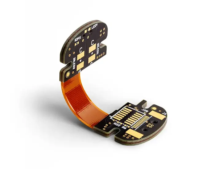
Manufacturing requirements must be defined separately for rigid areas and flexible connection areas.
Space and Weight Constraints
It is necessary to distribute the circuit across different planes or evaluate the possibility of reducing the number of wiring harnesses and connectors.
Multiple Circuit Interconnections
We hope to integrate some of the connections between discrete circuit boards into the board-level structure to reduce the number of separate connecting components.
Assembly Consistency
It is necessary to control the bending position, installation orientation, and relative dimensions to minimize assembly deviations.
System Cost Assessment
When comparing the costs of circuit boards, connectors, assembly, testing, and repair, you cannot determine which option is more cost-effective based solely on the type of board material.
03 / Machining Specifications
When confirming specifications, it is necessary to distinguish between rigid and flexible zones.
- Number of Floors
- Original scope: Floors 4–16; the number of floors in each area and their interconnections will be confirmed via the stacking plan.
- Material Systems
- FR-4, polyimide, and corresponding bonding materials; copper foil may be evaluated according to requirements such as RA/HTE
- Flexible Zone Thickness
- The original reference range is 0.05–0.8 mm; it is necessary to clarify how the copper layer, adhesive layer, and cover layer are included in this measurement.
- Line Width / Line Spacing
- The original minimum reference is 0.075 / 0.075 mm, subject to review based on copper thickness, material, and design.
- Drilling
- The minimum hole diameter is 0.1 mm; hole type, finished hole dimensions, and tolerances are to be confirmed separately.
- Surface Treatment
- OSP, gold plating, tin plating, and silver plating—select based on assembly and contact requirements
- Composite Structures
- Compatibility and processing conditions for RF, high-speed, or special-material mixed-pressing must be verified separately.
- Dimensions and Bending
- Provide flat-pattern drawings, bend-straight line diagrams, and forming diagrams; large-scale and dynamic bending operations are subject to project review.
The above serves as a reference for the original processing range; it should not be assumed that all limit parameters can be achieved simultaneously. The plate thickness in the rigid zone, the thickness in the flexible zone, and the thickness of local reinforcements should be specified separately.
04 / Engineering Review
Six Key Points to Confirm Before Production Begins
01
Exploded Views and Assembly Drawings
Provide both the plan view and the spatial relationships after assembly, and annotate the bend locations, directions, radii, and spacing between rigid areas.
02
Stiff-Flex Transition Zone
Verify boundary lines, overlay layers, and connection structures, and evaluate the relationship between pads, vias, and areas with sudden changes in thickness or bends.
03
Static or Dynamic Bending
Fixed and repetitive motion after installation require different evaluations. Dynamic requirements should specify the motion path, frequency, number of cycles, and environmental conditions.
04
Materials and Layering
Specify the materials, copper thickness, adhesive layers, cover films, and via connection methods for each area; for special mixed-pressing processes, confirm the process first.
05
Devices and Assembly Processes
Check the requirements for components, connectors, local reinforcements, and jigs to prevent interference after bending or damage to flexible areas during assembly.
06
Acceptance Testing and Reliability
Specify electrical measurements, impedance, external dimensions, and any necessary bending, thermal cycling, or vibration tests, and clearly define the conditions and acceptance criteria.
Do not fold flexible areas directly to create sharp creases. The bending angle, radius, and service life must be evaluated in the context of the overall structure and verified through agreed-upon testing.
05 / Request for Quotation Materials
Submit the drawings and operating conditions to the engineering team together.
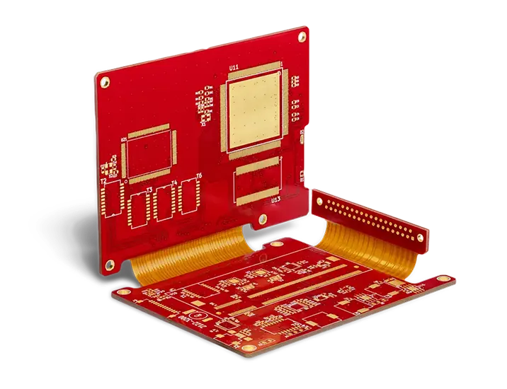
Product images illustrate structural types and do not represent uniform bending capacity or service life.
Manufacturing Documents
Gerber files, drill patterns, outline, and zone-specific layer stacks; specify materials, copper thickness, surface treatment, quantity, and version.
Structure and Movement
Drawings showing parting lines, cover films, local reinforcements, and assembly; specify whether static forming or dynamic motion conditions apply.
Delivery and Verification
Desired delivery date, test reports, and acceptance criteria; if assembly is required, please include the BOM, coordinates, and assembly instructions.
06 / Frequently Asked Questions
About Structure, Cost, and Bending
What is the difference between rigid-flex boards and FPCs with reinforcement?
Reinforcement primarily provides localized mechanical support; rigid-flex boards integrate rigid and flexible circuit areas within a single interconnect structure. This should be determined based on the layer stackup and electrical connection methods, rather than appearance alone.
Can both rigid-flex and rigid-rigid boards be bent continuously?
No. Many structures are designed to be formed only during assembly. Dynamic bending must be designed with specific considerations for the copper foil, laminate, bending radius, and operating conditions, and the target service life must be verified.
Is there a standard minimum bend radius?
This cannot be specified in isolation from the structure. It must be evaluated in conjunction with the thickness of the flexible area, the distribution of copper layers, the materials, the bending direction, and the number of bending cycles; the verification results under the agreed-upon conditions shall ultimately prevail.
Does reducing the number of connectors necessarily make the system more reliable?
Reducing the number of connection points may be beneficial for system design, but reliability still depends on the materials, the transition between rigid and flexible sections, assembly, stress, and the operating environment, and requires appropriate validation.
Do rigid-flex boards always reduce costs?
Not necessarily. Manufacturing costs may be higher; you should calculate the total cost by factoring in connectors, assembly, testing, rework, and order quantity, and then compare it with alternative solutions.
Is a complete 3D model required before providing a quote?
Not necessarily, but assembly drawings, bend directions, radii, and critical dimensions should be provided to adequately convey the structure. For complex three-dimensional structures, providing a model can help reduce ambiguity.
Once the prototype is approved, how do we move to mass production?
First, confirm the final document version, materials, lamination, assembly, and acceptance requirements; if structural or process changes occur, assess whether revalidation is necessary. Quantities and delivery arrangements will be quoted separately.
Shenzhen Jingpeng Electronics
Based on structural constraints, identify manufacturable connection solutions
Submit the stack-up, layout, and assembly specifications, and inquire about prototyping, manufacturing, and delivery arrangements for rigid-flex boards.
