

Automotive Electronics PCBs | From Installation Location to Batch Traceability
Cockpit, body control, lighting, and battery data acquisition modules are subject to varying temperature, vibration, power transients, and connectivity requirements. When reviewing automotive electronics PCBs, one should first define the module’s location and operating conditions, then specify materials, interconnects, assembly, and change control—avoiding the use of the term “automotive-grade board” as a substitute for a complete set of specifications.

Automotive Electronics-Related Exhibits | The specific scope of application will be determined on a project-by-project basis.
Depending on the installation location, the verification focus varies.
The following describes a method for breaking down requirements; it is not a general temperature rating or supply qualification table. The actual environmental limits are provided by the vehicle or module designer.
Cockpit and Infotainment
High-density processors, display interfaces, and wireless connections emphasize signal integrity and localized heat dissipation; at the same time, verify the fit between connectors, shielding covers, and instrument structures. Cockpit conditions cannot be directly applied to high-heat areas.
Body and External Joints
For car doors, lighting fixtures, and external control modules, it is especially important to clearly identify condensation and water ingress paths, as well as connector seals and mechanical fastenings. Coating is only one potential protective method; the enclosure and assembly boundaries should be confirmed first.
Battery Monitoring and Control
Distinguish between the battery cell voltage acquisition, balancing, communication, and high-voltage isolation zones; specify measurement accuracy, connection points, and abnormal operating conditions. The layout requirements for the high-voltage and low-voltage sections are determined by the comprehensive safety design.
Power and Lighting Control
The switch circuit, current-carrying connections, and heat-dissipating mounting surfaces collectively determine the local temperature rise; connectors or solder joints may become bottlenecks before the copper surfaces do, so the review must cover the entire current path from the input to the load.
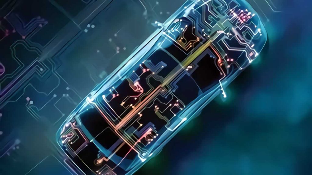

Images related to applications and manufacturing are used solely to illustrate the scenarios.
Break down “environmental resistance” into verifiable failure paths
Environmental testing should be based on the drawings and acceptance criteria. The following questions are intended to help develop a validation plan and cannot be used to directly determine a specific temperature, lifespan, or rating.
Thermal Cycling: It’s Not Just About Interconnects—It’s Also About Material Combinations
Expansion in the thickness direction of the board, variations in via structure, and differences in assembly materials may induce stress in the interconnects. Document the laminate, via-to-via transitions, and thermal processes, and determine inspection methods—such as cross-sectional analysis and continuity testing—based on project requirements.
Vibration: Starting with a heavy object and a fixed point
First, identify stress concentration points such as large inductors, connectors, and board-edge cantilevers; clarify the design requirements for screws, supports, potting compounds, or fastening materials. Simply increasing the board thickness may shift the problem to the solder joints or connectors.
Humidity Bias: Controlling Both Contamination and Distance Simultaneously
Condensation, residue, and residual voltage should be evaluated in conjunction with the actual environment. Identify high-resistance areas and specify cleaning and coating requirements; electrical changes before and after testing must correspond to the specific location and batch.
Transients and Electromagnetics: Interfaces and Reflux Cannot Be Separated
Power protection and filtering designs must be implemented at the component level, grounding connections, and wiring harness interfaces. PCB manufacturing is carried out in accordance with the approved documentation, and the transient and EMC results for the complete unit are still subject to system verification and validation.
Once the prototype has been approved, how can we ensure consistency in the mass-production version?
If a project requires PPAP or a customer-specific submission package, the list of items, responsibilities, and scope of what can be provided must be confirmed in advance; one cannot assume that the documentation is complete based solely on the industry name.
01
01|Freeze the Traceable Design Baseline
Link PCBs, BOMs, software, processes, and inspection versions; clearly specify materials, permitted substitutes, critical characteristics, and acceptance criteria. Prototype approvals should reference specific versions and samples.
02
02|Turning Error Reports into Controlled Changes
For changes to hole configurations, materials, supply sources, or assembly processes, assess the impact and obtain approval as agreed upon with the customer; do not resume production until the scope of re-inspection has been clearly defined, to avoid discrepancies between verbal agreements and the status of the drawings.
03
03|Verifiable Records of Batch-by-Batch Deliveries
Maintain records of agreed-upon batch identifiers, inspection reports, material certificates, and records of corrective actions for anomalies. If a customer requires more granular traceability, the method for establishing these links should be clearly defined before production scheduling, rather than retroactively creating unverifiable historical records after shipment.
Current Sampling Example: No Matter How Thick the Copper Is, Sampling May Still Be Accurate
This section discusses layout principles; it does not provide battery management control parameters.
The problem occurred during the measurement connection.
If the sampling line of a shunt resistor includes power copper traces or voltage drops at connection points, the measured voltage may not originate solely from the resistor itself. Changes in power current cause this error to vary with the load, and it cannot be resolved solely through software zero-point calibration.
Modify the layout and verification together
Based on the reference design for the selected device, use an appropriate Kelvin sampling connection to distinguish between the current-carrying path and the measurement path; compare data under different load, temperature, and connection conditions, and document the test setup to avoid masking differences caused by fixture wiring.
Map module functions to specific manufacturing routes
Refer to the following panel types and process inlets to further verify the specific structure, drawings, and acceptance requirements.
Thick-Copper PCB
When evaluating thick copper in the power output area, simultaneously check for pad necking, interlayer connections, and current-carrying limits of connectors; local hot spots and finished copper thickness requirements should be specified in the drawings, rather than simply listing the nominal copper foil weight.
Metal Substrate
Metal substrates can be evaluated for headlight heat dissipation, but the light source, insulating layer, thermally conductive interface, and lamp housing collectively form the thermal path; the flatness of the mounting surface and the screw areas also affect thermal contact.
HDI PCB
Cockpit processors or high-density control modules can evaluate HDI fan-out designs, first confirming the package, through-hole routing, and testability; complex interconnects should be selected in conjunction with a corresponding reliability verification plan.
Flex-Rigid Boards
When comparing cross-space connections to rigid-flex assemblies and inter-board connectors, focus on inspecting attachment points, stress relief, and the transition zones between rigid and flexible sections; assembly operations should not be confused with in-service motion.
Flexible PCB
When using FPC for battery connections or lighting assemblies, the contact points, reinforcements, insulation coverage, and installation paths must be specified; temperature variations and connection stresses should be included in product-level validation.
Radar PCB
Radar modules must be reviewed separately for operating frequency bands, stacking, copper foil, and critical route tolerances. Board names cannot be used as substitutes for RF structures, and processing requirements for antenna and feedline areas must be clearly labeled.
Inputs for the automotive project must be listed separately
Whether an industry project can be undertaken is subject to verification based on actual documentation, processes, and client onboarding and validation resources.
Environmental and Lifespan Tasks
Installation location, temperature variations, vibration conditions, humidity, and expected service life; specify the test methods, samples, and acceptance criteria—do not simply enter “automotive electronics.”
Supply and Documentation Requirements
Customer quality agreements, system certification requirements, specified materials, change notification procedures, and record retention provisions; certificates must be verified for the certified entity, scope, and validity period.
Key Electrical and Structural Components
Voltage, current conditions, insulation zones, critical dimensions, thermal interfaces, connectors, and mounting methods; must be the same version as the production drawings.
Automotive Electronics PCBs: Answers to Specific Questions
Does the use of automotive-grade components prove that a PCB is an automotive-grade product?
Component qualification, PCB manufacturing requirements, organizational quality systems, and module validation are distinct areas. Procurement specifications and evidence of compliance should be verified item by item and cannot be used as substitutes for one another.
Since the material also has a high Tg, can it be substituted directly?
It is also necessary to compare expansion, heat resistance, dielectric properties, processability, and supply conditions, and to confirm these in accordance with the project change process; the use of the same Tg designation does not prove that the materials are equivalent.
If the electrical tests are passed, is environmental validation still required?
Electrical testing of bare boards primarily verifies the specified connection and insulation requirements; it cannot fully cover the behavior of a fully assembled unit under temperature, vibration, and humidity conditions. The scope of verification is determined by the module requirements.
The reference materials are intended to help you understand the relevant technical principles; specific parameters and applicable conditions are subject to the project documentation and the corresponding device and material specifications.
TI: PCB Connection Methods for Low-Side Current SensingStart the Automotive Electronics Review with Module Placement and the Verification Plan
Shenzhen Jingpeng Electronics | Submit the application location, drawing version, operating conditions, and customer document requirements. First, verify eligibility and the scope of delivery, then determine the prototype and production plan.
