

With the continuous advancement of LED technology, the demand for high-power LEDs is growing. While meeting this demand, effective heat dissipation has become crucial. In the application of traditional LED heat sink substrates, Metal Core PCBs (MCPCBs) and ceramic heat sink substrates play a key role. However, there are some differences between them, particularly in terms of application scope and performance. This article will discuss these two types of heat sink substrates in depth and compare their applications in the COB (Chip on Board) process.
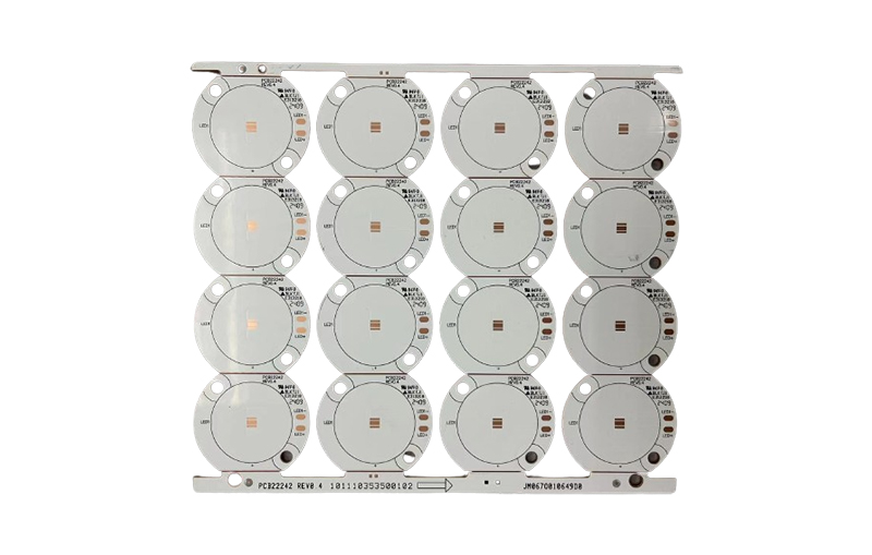
Advanced: Where Is the Thermal Resistance of a Heat Sink Substrate?
When evaluating a heat spreader, one cannot rely solely on the thermal conductivity; instead, one must consider the thermal resistance of the entire heat transfer path. Taking LEDs as an example, heat must pass through several stages in sequence to transfer from the junction to the environment:
| Segment | MCPCB | Ceramic Substrate (DPC) | Note |
|---|---|---|---|
| Chip-to-Substrate | The same | The same | It depends on the packaging and soldering |
| Circuit Layer | Copper foil, good thermal conductivity | Copper layer, good thermal conductivity | There isn't much of a difference |
| Insulation / Dielectric Layer | Polymer insulation layer, high thermal resistance | Ceramics are inherently insulating and thermally conductive. | This is the key difference |
| Grassroots | Aluminum or copper, which have good thermal conductivity | No independent grassroots organizations | MCPCB Base Layer Thickness |
| Go to the Radiator Interface | Interface materials required | Can be applied directly | Ceramics can reduce the number of interfaces by one |
The key is:The bottleneck of MCPCBs lies precisely in the insulation layer.. Aluminum and copper have very high thermal conductivities, but the polymer insulating layer sandwiched between them has a very low thermal conductivity, creating a bottleneck in the entire heat transfer path. In ceramic substrates, the ceramic material itself serves both as an insulator and a heat conductor, eliminating this bottleneck.
- The overall thermal conductivity is not the same as thermal performance: It also depends on the thickness of the insulation layer;
- Thinning the insulation layer reduces thermal resistance.: However, the pressure resistance also decreases accordingly;
- The fewer interfaces, the better.: Each additional interface adds another layer of thermal resistance.
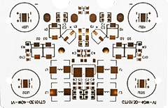
For an overview of metal substrates, seeMetal Substrate; For an introduction to aluminum substrates, seeIntroduction to and Applications of Aluminum Substrates。
MCPCB: Metal-Core Heat-Dissipating Substrate
The Evolution of MCPCBs
MCPCB originally evolved from traditional copper-clad printed circuit boards (FR4). The key difference from FR4 is that MCPCB utilizes metal as its core technology, employing aluminum or copper as the substrate, with a layer of copper foil or copper sheet attached to the substrate to form the circuit traces. This structure is designed to improve heat dissipation and address issues such as poor thermal conductivity.
Advantages of MCPCB
Aluminum inherently possesses good ductility and thermal conductivity; when combined with copper’s high thermal conductivity, it should theoretically provide excellent heat conduction and heat dissipation. However, since aluminum is a conductor itself, in order to prevent the copper circuits fromAluminum SubstrateTo ensure electrical conductivity between components, MCPCBs typically use polymeric materials as the insulating layer. However, the thermal conductivity of this insulating layer (polymer) is only 0.20.5 W/mK, and there are issues with heat resistance. Therefore, although aluminum and copper are excellent conductors of heat, the addition of polymer materials creates thermal resistance, which significantly reduces the substrate’s overall thermal conductivity, resulting in an MCPCB thermal conductivity of only 1 W/mK.2.2 W/mK. In addition, MCPCBs face issues related to metal expansion, which can lead to instability in the voltage withstand characteristics of LED products.
Advanced: A Comparison of Four Types of Ceramic Substrate Processes
| Process | Circuit Assembly Methods | Line Accuracy | Thermal Conductivity | Applicable |
|---|---|---|---|---|
| LTCC | Thick-Film Co-Firing | 低 | 中 | Multilayer, containing passive components |
| HTCC | Thick-Film Printing with High-Temperature Co-Firing | 低 | Upper-middle | Highly reliable, high-temperature resistant |
| DPC | Thin Film + Electroplating for Thickening | 高 | 高 | High-Power LEDs: The Mainstream |
| DBC / AMB | Direct Bonding of Copper Foil | 中 | 高 | Power Modules, High Current |
The original text mentions that LTCC and HTCC use thick-film processes and lack sufficient circuit precision, which is precisely why DPC has become so widespread.DPC uses thin-film and electroplating techniques to fabricate circuits, achieving a level of precision comparable to that of conventional PCBs....while retaining the inherent thermal conductivity advantages of ceramic, making it the mainstream solution for small, high-power LEDs.
- Accuracy Bottlenecks in Thick-Film Processes: Screen printing has a lower limit on line width, and sintering shrinkage causes dimensional deviations;
- The Precision Advantages of Thin-Film Processes: Lithography defines patterns, enabling the creation of fine lines;
- DBC's advantage lies in high current: The copper foil is thick and has high bond strength, making it suitable for power modules.
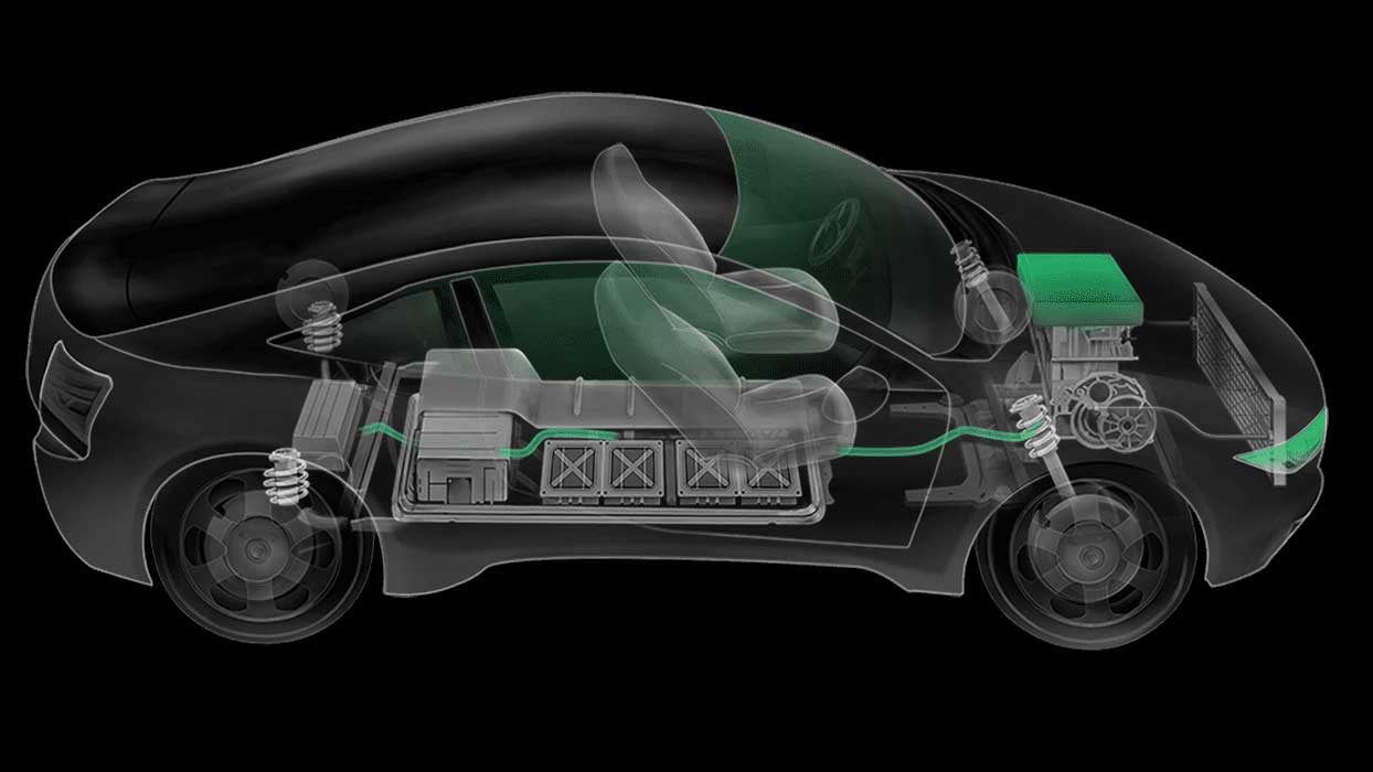
Applications of Ceramic SubstratesThe Widespread Use of Ceramic Substrates in the New Energy Automotive Sector; See LED aluminum substratesThe Role of LED Aluminum Substrates in Lighting Fixtures。
Ceramic Heat-Sink Substrates: Material Innovation
LTCC and HTCC
In recent years, many high-power LED heat sink substrates have begun to be made of ceramic materials. However, there are some differences between LTCC (Low-Temperature Co-fired Ceramics) and HTCC (High-Temperature Co-fired Ceramics). They use thick-film processes to fabricate metal circuits, which results in lower circuit precision. Due to process limitations, these materials are not suitable for manufacturing small-sized products. Therefore, current LTCC and HTCC process capabilities do not meet the demands of small-sized, high-power products.
DPC Ceramic Substrate
Compared to LTCC and HTCC, DPC ceramic substrates—which use thin-film lithography to fabricate metal lines—have a wider range of applications. This method offers higher line precision, better thermal conductivity, a smoother metal surface, and more uniform bonding between the metal and the ceramic.
Advanced: What Requirements Does the COB Process Place on Substrates?
COB (Chip on Board) involves mounting bare chips directly onto the substrate, eliminating the need for individual packages, resulting in lower thermal resistance and higher density. This also places higher demands on the substrate:
- Surface Flatness: When chips are directly bonded, an uneven substrate surface can cause voids and localized overheating;
- Line Accuracy: The dense arrangement of multiple chips requires finer circuit lines and smaller pads;
- Reflectance: Luminous efficiency is directly related to the reflectance of the substrate surface; white or highly reflective coatings are common choices;
- Thermal conductivity: Due to the high heat flux density per unit area, the substrate must dissipate heat rapidly;
- Thermal Expansion Matching: Differences in the coefficients of thermal expansion between the chip and the substrate can generate stress during temperature cycling.
Under these five requirements, the advantages of ceramic substrates are magnified:Smooth surface, fine circuit lines, good thermal conductivity, and a coefficient of thermal expansion closer to that of the chip. The advantages of MCPCB, however, lie in its low cost and lack of size restrictions; it remains the most cost-effective option for applications involving large areas and moderate heat flux densities.
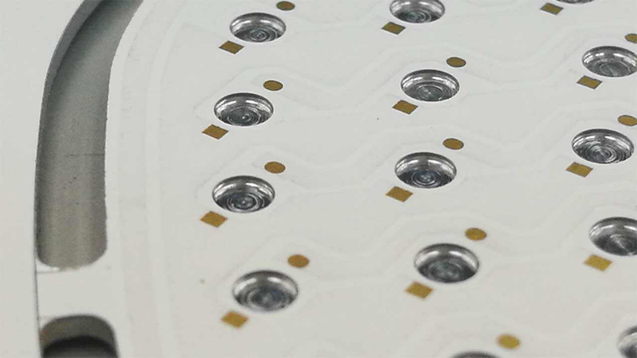
For high-efficiency cooling solutions, seeHigh-Efficiency Heat Dissipation Solutions for Aluminum Substrates; For thermal analysis methods, seeThe Importance of Thermal Analysis and Modeling in PCB Design。
Conclusion
In high-power LED thermal management applications, both MCPCBs and ceramic heat spreaders offer distinct advantages. MCPCBs feature a traditional metal-core structure, but their thermal conductivity is somewhat limited by the insulating layer. Ceramic heat sink substrates, which utilize different materials and manufacturing processes, can offer better circuit precision and thermal conductivity, but are limited by size and manufacturing constraints. The choice of heat sink substrate depends on the specific application requirements. In any case, as LED technology continues to advance, both types of heat sink substrates will continue to play a critical role in ensuring the reliability and performance of LED products.
Advanced: Five Steps to Determine Which Heat Sink Substrate to Use
- Calculate the heat flux density: Heat output divided by heat-emitting area—this is the starting point for selection;
- Target Condensation Temperature: Determine the maximum allowable junction temperature based on service life requirements;
- Backward-calculated allowable thermal resistance: The difference between the junction temperature and the ambient temperature divided by the power;
- Comparison of Thermal Resistance Measurement Methods: MCPCB, DPC ceramic, and DBC are accounted for separately;
- Apply Cost and Size Constraints: Select the lowest-cost, dimensionally feasible option from among those that meet the thermal resistance requirements.
| Scene | Recommended Solutions | Reason |
|---|---|---|
| Large area, moderate heat flux density | MCPCB | Low cost, no size restrictions |
| Compact size, high power density | DPC Ceramics | Balancing Circuit Accuracy and Thermal Conductivity |
| Power Modules, High Current | DBC / AMB | Thick copper foil, high bond strength |
| Passive components need to be embedded | LTCC | Can be co-fired in multiple layers |
| Extremely cost-sensitive | FR-4 + Heat-Dissipating Vias | This is only feasible when the heat flux density is low. |
The key point isQuantify First, Then Select the Model. Based on experience, choosing a ceramic or metal substrate right away often leads to either higher costs or inadequate thermal design—both of which are common.
Advanced: Differences in Reliability Between Two Types of Substrates
- Heat Aging: The polymer insulation layer in MCPCBs gradually ages under prolonged high temperatures, leading to a decline in thermal conductivity and insulation performance; ceramic materials are inherently heat-resistant and pose a much lower risk of aging;
- Temperature Cycling: In MCPCBs, there is a significant difference in thermal expansion between the metal substrate and the copper traces, which can cause the insulation layer to delaminate after long-term cycling; ceramic substrates have thermal expansion properties closer to those of the chip, resulting in a longer cycle life;
- Mechanical Strength: Metal-based materials have good impact resistance, while ceramics are brittle and require precautions to avoid stress concentration and edge impacts;
- Dielectric Strength Stability: The dielectric strength of MCPCBs decreases as the insulation layer ages, whereas the dielectric properties of ceramic substrates remain stable over the long term.
In applications requiring long service life, high temperatures, and high reliability, the advantages of ceramic substrates often outweigh their cost disadvantages; whereas in applications at room temperature, with modest service life requirements, and where cost is a key consideration, MCPCBs remain the more practical choice.

For SMT equipment selection, seeHow to Choose the Right SMT Placement Machine; For the material system, seePCB Materials。
Frequently Asked Questions (FAQs)
- What is the difference between MCPCB and ceramic heat spreader substrates? MCPCBs use metal as their core, while ceramic heat-dissipating substrates are made of ceramic materials. They differ in terms of thermal conductivity and range of applications.
- Why are the thermal conductivity properties of MCPCBs limited? The thermal conductivity of MCPCBs is affected by the insulating layer material, which has a low thermal conductivity.
- What are LTCC and HTCC ceramic substrates? LTCC and HTCC are two ceramic fabrication processes used to manufacture heat-dissipating substrates. They have different characteristics and applications.
- Why are DPC ceramic substrates more popular in high-power LED applications? DPC ceramic substrates offer higher circuit precision and thermal conductivity, making them suitable for small, high-power LED products.
- How do I choose a heat sink substrate that's right for my application? The selection of a heat sink substrate should be based on specific application requirements, including factors such as size, thermal conductivity, and process requirements.
6. Why can't ceramic substrates be made larger?
This is primarily limited by the sintering process and the brittleness of the material. Ceramics shrink during the sintering process, and the larger the dimensions, the more difficult it is to control shrinkage and deformation; at the same time, large ceramic wafers are more prone to cracking during machining and assembly. Therefore, ceramic substrates are typically small to medium in size, while large-area applications still primarily rely on metal substrates.
7. Do ceramic substrates require an additional insulating layer?
No, ceramic is inherently an excellent insulator, which is precisely one of its key advantages over MCPCBs. Because MCPCBs have a conductive metal substrate, they require an additional layer of insulating material, and this layer is the primary source of thermal resistance. Ceramic substrates eliminate this layer, resulting in a shorter thermal path.
8. What is the approximate cost of a DPC ceramic substrate?
Significantly higher than MCPCBs—typically several times higher or even more, depending on size, circuit precision, and production volume. Whether it’s worth it depends on thermal design requirements: when the heat flux density exceeds the capacity of an MCPCB, the performance gains from switching to ceramic often far outweigh the additional cost and can also reduce the need for heat sinks.
9. Can through-holes be made in ceramic substrates?
Yes, but the manufacturing process differs from that of conventional PCBs. Common methods include laser drilling followed by metallization, which is relatively expensive and has limitations regarding hole size and placement. Therefore, the number of vias on ceramic substrates should be minimized as much as possible, and interconnections should be concentrated on a single side through proper layout.
10. What are the consequences of a mismatch in thermal expansion coefficients?
During temperature cycling, differences in thermal expansion between the chip and the substrate can generate shear stress at the solder joint. Over time, this can lead to cracking of the solder layer, enlargement of voids, or even chip detachment. Selecting a substrate material with a thermal expansion coefficient closer to that of the chip (e.g., ceramic is preferable to aluminum) can significantly improve the temperature cycling life.
11. How should the issue of voltage resistance in metal substrates be understood?
The insulating layer of an MCPCB serves both to conduct heat and to provide electrical insulation; reducing its thickness improves thermal conductivity but lowers voltage withstand capability, creating a trade-off. Insufficient voltage withstand capability poses safety risks and reliability concerns; particularly in products with mains power input, sufficient margin must be maintained in accordance with safety regulations, and the thickness should not be reduced solely for the sake of heat dissipation.
Additional Information:How to Choose the Right SMT Placement Machine · The Widespread Use of Ceramic Substrates in the New Energy Automotive Sector
