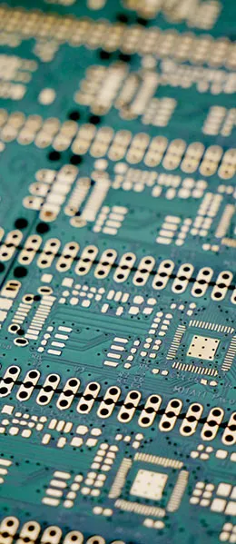
Printed circuit boards (PCBs) are a critical component of electronic devices, providing support and connections for electronic components. PCBs can be classified into single-sided, double-sided, and multilayer boards based on different criteria, and can also be categorized according to the type of substrate intoFlexible PCBFlexible PCBs, rigid PCBs, and rigid-flex PCBs. In this article, we will provide a detailed overview of these different types of PCBs, as well as their characteristics and applications.
Advanced: There Are Actually Three Dimensions to PCB Classification
The number of layers and the substrate are the two most common classification criteria, but in engineering communication, there is a third dimension—Applications and Process Characteristics. Only by considering all three together can we avoid any ambiguity regarding "what this board is called":
| Classification Dimensions | Main Categories | Questions Answered |
|---|---|---|
| By Number of Circuit Layers | Single-sided boards, double-sided boards, multilayer boards | Is there enough space for wiring, and what is the cost? |
| By Substrate Type | Rigid Boards, Flexible Boards, Rigid-Flex Boards | Can it be bent, and will it fit into the structure? |
| By Application and Process | HDI, high-frequency boards, metal-core boards, thick-copper boards, package substrates | Will the signal rate, heat dissipation, and current-carrying capacity be sufficient? |
These three dimensions are orthogonal: a board can be “8-layer + rigid-flex + HDI” at the same time. Therefore, when placing an order, the safest way to describe it isClearly describe all three dimensions, rather than just mentioning a product category.
- Number of FloorsDetermine the wiring resources and cost; for each additional layer, the lamination and drilling processes must be repeated;
- SubstrateTo determine the mechanical properties and temperature resistance, polyimide is used for the flexible sections, and epoxy-impregnated glass cloth is used for the rigid sections;
- Process GradeDetermine the performance requirements for minimum trace width and spacing, blind and buried vias, impedance control, and other factors.
For information on how to select a panel system, seeHow to Choose the Right PCB Material Based on PCB Type; For a comparison of the properties of three common types of rigid copper-clad laminates, seeA Comparison of the Properties of the Three Most Common Types of Rigid Copper-Clad Laminates。
I. Classification by Number of Circuit Layers
1. Single-sided board
Single-sided PCBs are one of the simplest types of PCBs. On a single-sided PCB, all components and traces are located on the same side. Therefore, certain restrictions must be followed when designing single-sided PCBs, as traces cannot cross and must be routed along separate paths. This type of PCB was commonly used in early circuit designs but is less common in today’s complex electronic devices.
2. Double-sided board
Unlike single-sided boards, double-sided boards have traces on both sides. To connect the traces on both sides, through-holes must be created on the PCB. Through-holes are small holes filled or plated with metal that connect the traces on both sides. The advantage of double-sided PCBs is that they can be used for more complex circuit designs, as the traces can crisscross and connect on both sides.
3. Multilayer Board
Multilayer boards are designed to increase the area available for circuit layout. They consist of multiple double-sided boards, with a layer of insulating material between each board. The name “multilayer board” typically refers to the number of distinct circuit layers, usually including the two outermost layers. Common multilayer boards have 3 to 6 layers, but complex designs may have as many as a dozen layers. Multilayer boards are widely used in modern electronic devices because they allow for more complex circuit designs and higher levels of integration.
Advanced: How Do You Determine the Number of Layers?
"How many layers should this board have?" is a question that must be answered before providing a quote. The basis for this decision is not the number of components, but ratherCan the wiring be completed within one or two floor changes, and is a complete reference plane required?:
| Number of Floors | Typical Applications | Cabling Characteristics | Relative Cost |
|---|---|---|---|
| Single-sided | Simple home appliances, small power supply boards, indicator light boards | Wires must not cross; use jumpers to resolve this. | Lowest |
| Double-sided | General-Purpose Control Boards, Small Consumer Electronics Devices | By changing layers via vias, it is possible to stagger the routing. | 低 |
| Fourth Floor | Digital board with an MCU and speed requirements | The middle two layers serve as the power and ground planes. | 中 |
| Floors 6 through 8 | High-Speed Interfaces, Multiple Power Supplies, Complex FPGAs | Signal layers and ground planes are arranged alternately | Upper-middle |
| 10 stories or more | Telecommunications equipment, server motherboards, backplanes | Numerous plane layers, emphasizing impedance and crosstalk | 高 |
Four Practical Criteria:
- BGA Fan-Out: BGAs with a pitch of less than 0.8 mm often require four layers or more for fan-out;
- Signal Rate: Once the rising-edge duration reaches the nanosecond range, a adjacent reference plane must be configured for high-speed signals;
- Types of Power Supplies: The more power rails there are, the greater the need for dedicated plane layers; otherwise, power integrity is difficult to ensure;
- Cost Sensitivity: Even-numbered layers are cheaper than odd-numbered layers—odd-numbered layers require a balancing layer, which makes them prone to warping when pressed.
The last one is especially easy to overlook:Try to design it with an even number of layers.. There is little difference in the manufacturing difficulty between the fifth and sixth layers, but the sixth layer typically offers significantly better yield and lead time.
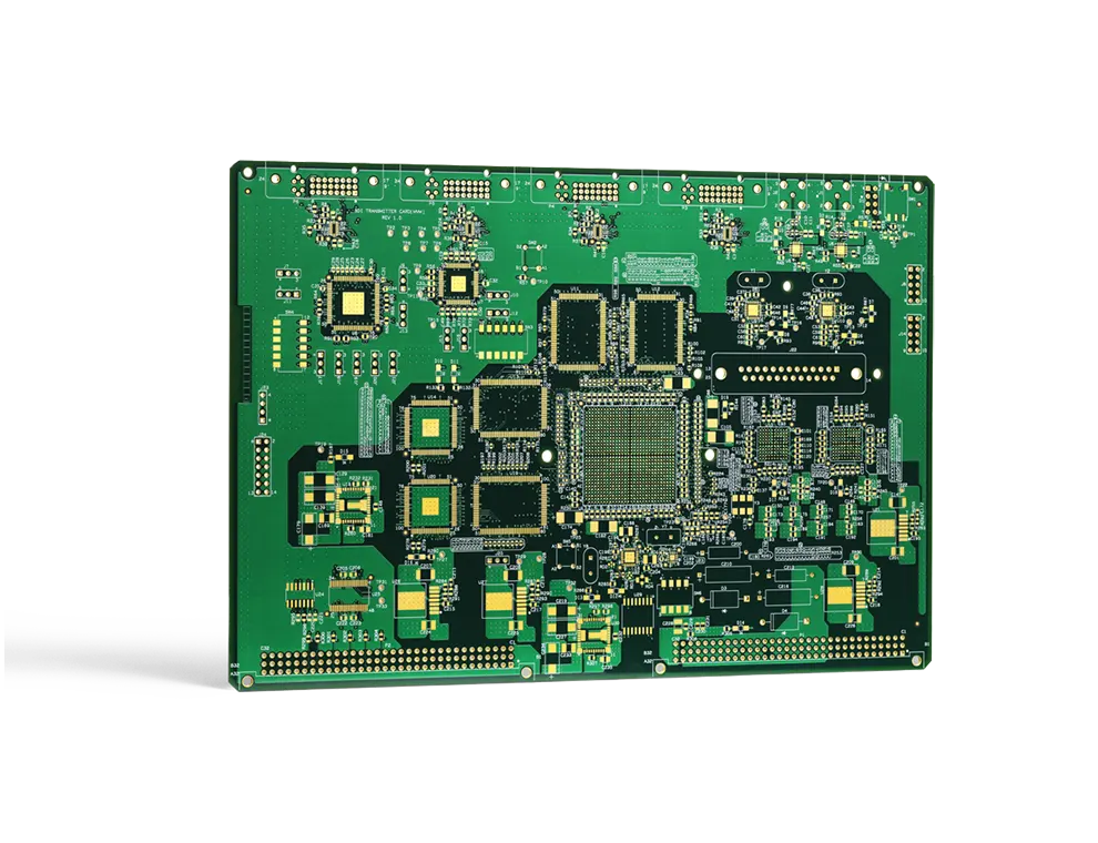
For specific methods of determining the number of layers, seeHow to Determine the Number of PCB Layers; For key points on high-layer lamination, seeLamination Process: The Heart of High-Layer-Count PCB Manufacturing。
II. Classification by Substrate Type
1. Flexible PCBs (Flex Boards)
Flexible PCBs are made from flexible substrates and are bendable, making them suitable for electronic components that require flexibility. Flexible PCBs are widely used in fields such as aerospace, military, and mobile communications. Their flexibility makes them ideal for applications requiring three-dimensional assembly.
2. Rigid PCBs
Rigid PCBs are made from rigid substrates and do not bend easily. They typically use paper-based or glass cloth substrates, with copper foil bonded to the surface, which is then laminated and cured. Rigid PCBs provide stable support for the electronic components mounted on them. This type of PCB is widely used in a variety of electronic devices.
3. Rigid-Flex PCBs (Rigid-Flex Boards)
Rigid-flex PCBs are a special type of PCB that combines rigid and flexible areas. This structure allows the PCB to offer both the structural support of a rigid PCB and the bending capabilities of a flexible PCB. As a result, rigid-flex PCBs are ideal for applications that require complex shapes and three-dimensional assemblies.
Advanced: Four Considerations for Selecting Substrates
Flexible, rigid, and a combination of rigid and flexible are not simply a matter of choosing one of three options; there are four questions that need to be answered:
- Does it need to be bent?: The requirements for materials and copper foil are completely different between applications that involve a single bend during assembly (bend-and-install) and those that require repeated dynamic bending (such as the hinge area of a foldable screen); for the latter, rolled copper must be selected and the bending radius must be controlled;
- What is the operating temperature?: Standard FR-4 has a glass transition temperature of approximately 130–140 °C; for lead-free reflow and high-power applications, materials with a high Tg or polyimide should be selected;
- How high is the signal frequency?: At the GHz level, pay attention to the dielectric constant and the tangent of the loss angle; with standard FR-4, losses at high frequencies will significantly erode the signal margin;
- Heat Dissipation and Current-Carrying Requirements: For high-power applications, consider using a metal substrate or thick copper; thermal conductivity is achieved through a combination of the copper foil thickness and the substrate's thermal conductivity.
Rigid-flex boards are the most challenging of the three types to design and manufacture. They integrate rigid and flexible sections into a single board, eliminating the need for connectors and wiring harnesses and offering higher reliability. However, the lamination, drilling, and forming processes must be tailored to each material, resulting in longer lead times and higher costs.
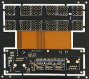
For a detailed analysis of rigid-flex boards, seeWhat Is a Rigid-Flex Board?; For application scenarios of flexible boards, seeFlexible PCB。
In summary, there are many different types of PCBs, and each type has its own specific applications and advantages. Choosing the PCB type that best suits your project’s needs is crucial, as it will directly impact the complexity and performance of your circuit design.
Advanced: Special Categories Categorized by Use
In addition to the number of layers and the substrate, there are a number of categories in engineering that are named based on their manufacturing process or intended use, which are frequently encountered during the selection process:
| Category | Key Features | Typical Applications |
|---|---|---|
| HDI Board | Micro-blind vias, fine line widths, interconnects on any layer | Cell Phone Motherboards, Portable Devices |
| High-Frequency / Microwave Boards | Substrates with Low Dielectric Constant and Low Loss | Base station antennas, radar, satellites |
| Metal substrates (aluminum-based, etc.) | Thermal Conductivity of the Metal Core Layer | LED Lighting, Power Modules |
| Thick Copper Board | Copper thickness ≥ 2 oz, high current-carrying capacity | Power Supplies, Automotive Electronics, Industrial Drives |
| Package Substrate (IC Carrier) | Ultra-fine circuits, with line widths as small as tens of micrometers | Chip Packaging |
| Hybrid Pressure Plate | Different substrates laminated into a single stack | Systems in Which High-Frequency and Low-Speed Circuits Coexist |
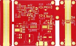
There is also overlap between these categories; for example, using different materials to create separate zones on the same board for “high-frequency + mixed-voltage” applications is a common practice that balances performance and cost. For mixed-voltage boards, special attention must be paid to the differences in the coefficients of thermal expansion between the two materials, and the lamination parameters require specific adjustments.
For the HDI manufacturing process, seeA Comprehensive Analysis of the HDI PCB Manufacturing Process; For information on the trade-off between board thickness and copper thickness, seeBoard Thickness and Copper Thickness in PCB Design。
If you need custom PCBs, multilayer PCB manufacturers will provide professional solutions tailored to your needs to ensure optimal performance and quality.
Advanced: Five Steps to Determine Which Type of PCB You Need
- Determine the shape first: Determine whether bending is required and whether there are space constraints, and then decide whether to use a rigid, flexible, or combined rigid-flex design;
- Specify the number of layers again: Estimate based on BGA fan-out, signal speed, and power supply type, and use even numbers whenever possible;
- Then select the substrate: Select the grade and brand of the sheet material based on temperature resistance, frequency, loss, and thermal conductivity requirements;
- Specify the process grade: Minimum trace width and spacing, hole diameter, whether blind or buried vias are required, and whether impedance control is needed;
- Final Production Capacity Alignment: Submit the above requirements to the manufacturer for a process feasibility assessment to avoid designing solutions that cannot be mass-produced.
The value of Step 5 is often underestimated. Even for the same stacking configuration, there can be significant differences in equipment capabilities among different manufacturers; holding a process discussion with the manufacturer before the design freeze can often save a round of board revisions.
- The list of specifications must be clearly stated.: Number of layers, dimensions, board thickness, copper thickness, substrate, surface treatment, impedance requirements, quantity, delivery date;
- The documents must be complete.: Gerber files, drill files, stack-up specifications, and impedance tables are all essential;
- Please let us know about any special requests in advance.: Blind vias, through-hole vias, resin-filled vias, and gold finger chamfers, among others, can all affect production lines and delivery schedules.
Before placing an order, compile this information into a specifications list (number of layers, dimensions, board thickness, copper thickness, substrate, surface treatment, impedance requirements, quantity, and delivery date). This will significantly improve the accuracy of the quote and delivery date.
Conclusion
PCBs play a crucial role in modern electronic devices, and different types of PCBs are suitable for different applications. Whether they are single-sided, double-sided, or multilayer boards, or flexible, rigid, or rigid-flex boards, each type has its own unique characteristics and advantages. Selecting the PCB type that best suits your project’s needs is key to ensuring the performance and reliability of your electronic devices.
Advanced: PCB and PCBA Are Not the Same Thing
Two concepts that are often confused in communication:PCB refers to a bare board, i.e., a circuit board with the circuit patterns and surface treatment completed but with no components yet mounted;PCBA refers to a component after assembly is complete., that is, a finished product with components soldered onto a bare board.
- Different Deliverables: PCBs are delivered as bare boards, while PCBA units are delivered as functional modules;
- The test items are different: Bare boards are primarily subjected to electrical testing and visual inspection, while PCBA units also undergo functional testing and aging tests;
- Different Scopes of Responsibility: Issues with bare boards are the responsibility of the board manufacturer, while soldering and component issues are the responsibility of the assembly plant; clearly defining these boundaries facilitates accountability.

For methods of evaluating the quality of bare boards, seeThree Key Metrics for PCB Manufacturing and Methods for Quality Assessment; For an overview of the materials system, seePCB Materials。
Frequently Asked Questions
1. What are the different types of PCBs?
PCB boards can be classified into single-sided, double-sided, and multilayer boards, as well as flexible boards, rigid boards, and rigid-flex boards, among other types.
2. What is a pilot hole?
Via holes are small holes that connect conductors on a double-sided board; they are filled or coated with metal to establish a connection between the conductors.
3. In which fields are flexible PCBs widely used?
Flexible PCBs are widely used in the aerospace, military, and mobile communications sectors, and are suitable for electronic components that require flexibility.
4. What are the advantages of rigid PCBs?
Rigid PCBs provide stable support and are suitable for applications that require the secure mounting of electronic components.
5. Why choose a rigid-flex PCB?
Rigid-flex PCBs combine the characteristics of both rigid and flexible boards and are suitable for applications requiring complex shapes and three-dimensional assemblies.
6. Are multilayer boards always better than double-sided boards?
Not necessarily. Multilayer boards offer better routing capabilities and electromagnetic compatibility, but they also come with higher costs, longer lead times, and greater manufacturing complexity. If a double-sided board can meet the routing and performance requirements, there is no need to use a multilayer board; multilayer boards are only an essential choice when a complete reference plane, BGA fan-out, or strict crosstalk control is required.
7. Why are composite panels so expensive?
The key challenge lies in the manufacturing process: the rigid and flexible areas must be processed separately; the parameters for the two materials differ during lamination; and drilling and forming must also be controlled independently. Additionally, the yield rate is lower than that of standard rigid boards. In return, this approach offers advantages in terms of size, weight, and reliability by eliminating the need for connectors and wiring harnesses.
8. How many times can a flexible board be bent?
This depends on the bend radius, the type of copper foil, and the bending method. For dynamic bending applications, use rolled copper and avoid placing vias in the bend area; keeping the bend radius within the material’s permissible range during the design phase is critical to determining the board’s service life. Specific requirements should be confirmed with the manufacturer.
9. Can standard FR-4 be used for high-frequency boards?
This is acceptable for applications below a few hundred MHz, where trace lengths are short and loss requirements are not stringent. However, at the GHz level, FR-4’s dielectric constant drifts with frequency, and its tangent of the loss angle is relatively high, which significantly degrades signal integrity; in such cases, specialized high-frequency substrate materials should be used instead.
10. Can you provide a quote based solely on a schematic provided by the manufacturer?
We can provide a rough estimate, but an accurate quote requires complete specifications: number of layers, dimensions, board thickness, copper thickness, base material, surface treatment, minimum line width, line spacing, and hole diameter; whether impedance control is required; quantity; and delivery date. The more complete the information, the closer the quote and delivery date will be to the actual figures.
11. Have single-sided boards been phased out?
No. In scenarios where cost is a major concern and the circuitry is simple, single-sided PCBs still offer a cost advantage—for example, in certain home appliance control boards, small power supply boards, and indicator light boards. Their limitation is that traces cannot cross, so they cannot accommodate highly complex designs.
Further Reading:Common Issues and Solutions for the Laminating Process of Multilayer Printed Circuit Boards · Challenges in the Manufacturing of High-Layer-Count Printed Circuit Boards and Key Production Process Controls