

With the continuous advancement of LED technology, LED lighting has become the mainstream choice for energy efficiency and environmental protection. However, heat dissipation has long been one of the challenges faced by LED manufacturers. To address this issue, aluminum substrates have emerged as a widely adopted solution. This article will take an in-depth look at LED heat dissipation and the role of aluminum substrates in addressing this challenge.
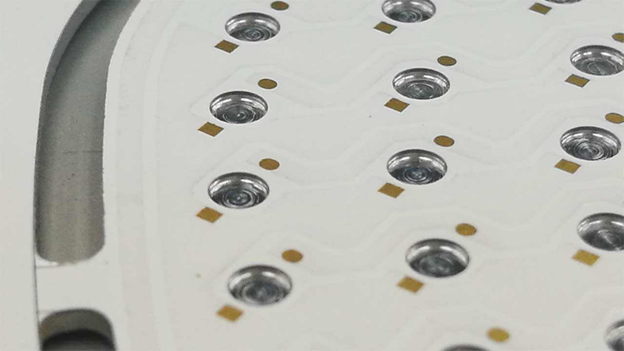
Table of Contents
- The Challenges of LED Heat Dissipation
- Characteristics of Aluminum Substrates
- Structure of an LED Aluminum Substrate
- Applications of LED Aluminum Substrates
- How to Choose the Right LED Aluminum Substrate
- Frequently Asked Questions
- Conclusion
The Challenges of LED Heat Dissipation
An LED is a semiconductor device that generates heat when in operation. If heat dissipation is inadequate, excessive temperatures can reduce the LED’s performance and lifespan, and may even cause the LED component to fail. Therefore, LED heat dissipation is critical to the reliability and performance of LED products.
Advanced: LED Heat Dissipation Should Be Calculated Based on the Thermal Resistance Chain
When it comes to LED heat dissipation, it’s not enough to simply rely on the “good thermal conductivity of aluminum substrates”; it’s a processThermal Resistance Chain: Heat travels from the chip’s junction, passing sequentially through the die-attach layer, the device heat sink, the solder bumps, the interconnect layer, the insulating layer, and the aluminum base layer, before finally reaching the heat sink and dissipating into the environment. If the thermal resistance is too high at any stage, the junction temperature cannot be reduced.
- Junction temperature (Tj) is a key metric: The light decay and lifespan of an LED are directly determined by the junction temperature; for every increase in junction temperature, the decline in lifespan becomes very noticeable;
- The insulation layer is often the greatest thermal resistance.: The thermal conductivity of the aluminum substrate is very high (on the order of 200 W/m·K), while the insulation layer typically has a thermal conductivity of only 1–3 W/m·K, making it the bottleneck in the entire thermal path;
- The interface and the welded layer must not be overlooked: Voids, cold solder joints, or uneven application of thermal interface material can all cause the actual thermal resistance to be significantly higher than the theoretical value.
| Segment | Thermal Resistance Contribution | Optimization Methods |
|---|---|---|
| Chip-to-Device Heat Sink | Determined by the device package | Choose a low-thermal-resistance package |
| Solder Joints / Die Attach Layer | Smaller, but prone to cavities | Controlling the Weld Porosity Rate |
| Circuit Layer (Copper Foil) | 小 | Increase the thickness of the copper foil as appropriate |
| Insulation Layer | Maximum | Choose a medium with high thermal conductivity and reduce the thickness |
| Aluminum Substrate | Very small | Ensure a good fit with the heat sink |
| From the heat sink to the environment | Determined by the system | Increase the heat dissipation area and optimize the airflow path |
The conclusion is straightforward:When selecting an aluminum substrate, the thermal conductivity and thickness of the insulating layer are more important considerations than whether the insulating layer is thicker than the aluminum base layer.. Spending your budget on insulation is often more effective than thickening the aluminum base.
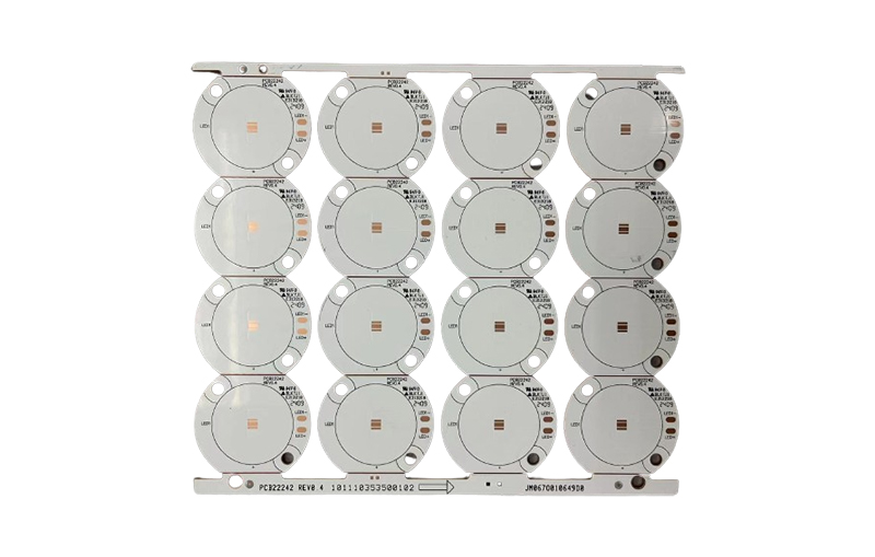
For a general classification and uses of metal substrates, please refer toMetal SubstrateOne page.
Characteristics of Aluminum Substrates
1. Uses surface-mount technology (SMT)
LED aluminum substrates utilize SMT technology, which enables high-density assembly, improves production efficiency, and reduces manufacturing costs.
2. Effective thermal diffusion treatment
In circuit design, LED aluminum substrates provide highly effective thermal diffusion, rapidly conducting the heat generated by the LEDs to the aluminum substrate, thereby reducing the operating temperature of the LEDs.
3. Improve product power density and reliability
The excellent heat dissipation properties of LED aluminum substrates can lower the operating temperature of LEDs, thereby improving the power density and reliability of LED products and extending their service life.
4. Reduce the product's size
LED aluminum substrates effectively dissipate heat, so they do not require large heat sinks, which allows for smaller, more compact LED products.
5. Alternative to Ceramic Substrates
LED aluminum substrates can replace traditional, fragile ceramic substrates and offer better mechanical durability.
Advanced: Selection Parameters for Each Layer of the Three-Layer Structure
The three layers of an aluminum substrate each have specific specifications and design trade-offs in engineering:
| 层 | Common Sizes | Key Considerations for Selection |
|---|---|---|
| Circuit Layer (Copper Foil) | 1 oz–10 oz | Thick copper is used for high currents, but the capacity of fine traces decreases accordingly. |
| Insulation Layer | Thermal conductivity: 1–3 W/m·K; thickness: 50–200 μm | This layer is the most critical one, as it determines both the voltage withstand capacity and thermal resistance. |
| Base (Aluminum / Copper) | Aluminum 5052 / 6061 (common grades), 1.0–3.0 mm thick | Aluminum is lightweight and has good thermal conductivity; copper has even better thermal conductivity but is heavy and expensive. |
Among these, there are two trade-offs that are most easily overlooked:
- The thinner the insulation layer, the lower the thermal resistance; however, the voltage withstand rating and reliability will decrease....it is necessary to strike a balance between voltage withstand requirements (typically 2–4 kV) and thermal performance;
- The thicker the copper foil, the higher the current-carrying capacity; however, the capacity of fine traces decreases....The minimum line width that can be reliably produced on 10-ounce copper is significantly greater than that on 1-ounce copper.
There is also another categoryThermoelectric Separation Structure: By mounting the LED’s thermal pad directly onto the exposed aluminum substrate (after locally removing the insulation layer), thermal resistance can be significantly reduced. This is a common practice for high-power-density products, though it comes at the cost of a more complex manufacturing process and the need to reevaluate the insulation design.
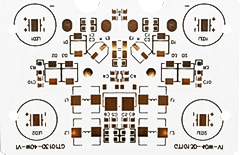
For information about the panels themselves, seeWhat material is aluminum substrate sheet made of?。
Structure of an LED Aluminum Substrate
The structure of an LED aluminum substrate consists of three layers:
- Circuit Layer: This layer is equivalent to the copper-clad laminate in a standard PCB and is used to form the LED circuitry. The thickness of the copper foil for the circuit traces typically ranges from 1 oz to 10 oz.
- Dielectric Layer (Insulating Layer): An insulating layer is a thermally conductive insulating material with low thermal resistance that is used to separate the circuit layer from the substrate, ensuring that the circuit is not affected by heat.
- Base Layer: The grassroots level isMetal Substrate, typically aluminum or copper. Aluminum substrates are commonly used in LED applications because aluminum has high thermal conductivity, which helps dissipate heat quickly.
Advanced: How to Choose Between Aluminum, FR-4, and Ceramic Substrates
| Comparison Items | Aluminum Substrate | FR-4 | Ceramic Substrate |
|---|---|---|---|
| Thermal conductivity | High (on the order of 1–3 W/m·K for a solid plate) | Low (approximately 0.3 W/m·K) | High (Al₂O₃ approx. 24, AlN approx. 170 W/m·K) |
| Mechanical Strength | Good, shatter-resistant | 好 | Brittle, fragile |
| Cost | 中 | 低 | 高 |
| Machinability | Can be rimmed; V-Cut restricted | Best | Poor |
| Dielectric Strength | It depends on the insulation layer | 好 | 好 |
| Applicable Scenarios | Medium- to High-Power LEDs, Power Supply Modules | Low-Power Electronic Devices | Ultra-high power density, high frequency, and high reliability |
Converging based on power density is the fastest way to make a judgment:
- Low power density, cost-sensitive: FR-4 with thermally conductive vias is usually sufficient; there is no need to use an aluminum substrate;
- Standard LED Lighting and Power Supply Modules: Aluminum substrates offer the best value for the money and are the default choice;
- Very high power density or extremely stringent thermal resistance requirements: Consider ceramic substrates or aluminum substrates with a thermoelectric separation structure.
It is important to note in advance that aluminum substrates generallyThrough-hole plating interconnects cannot be made in the same way as on FR-4.(Unless special insulation measures are taken), multi-layer interconnect solutions are limited; this is why they are primarily used on single-sided and double-sided power boards.
Applications of LED Aluminum Substrates
LED aluminum substrates are widely used in the following fields:
- Audio Equipment: Including input amplifiers, output amplifiers, audio amplifiers, and others.
- Power Equipment: Used in switch-mode regulators, DC/AC converters, switching regulators, etc.
- Communications and Electronic Equipment: Suitable for high-frequency amplifiers, filters, transmitter circuits, and the like.
- Office Automation Equipment: Including motor drivers, etc.
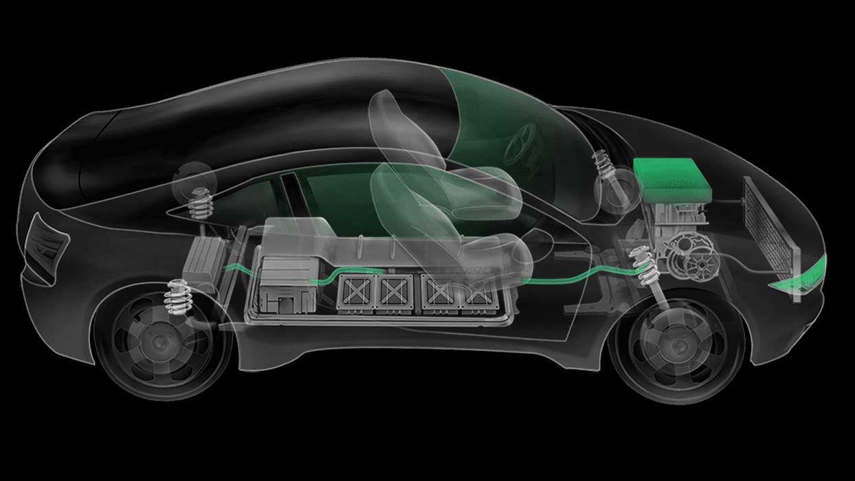
- Automotive Electronics: Used in electronic regulators, igniters, power controllers, etc.
- Computer: Suitable for CPU boards, floppy disk drives, power supplies, and other components.
- Power Module: Commonly used in applications such as power converters, solid-state relays, and rectifier bridges.
Advanced: Breaking Down the Selection Process into Five Quantifiable Steps
- Calculate the thermal budget: Determine the allowable total thermal resistance based on the LED power and the target junction temperature;
- Fixed Insulation Layer: Determine the thermal conductivity and thickness based on thermal resistance and voltage withstand requirements;
- Determine the thickness of the copper: Select a value between 1 oz and 10 oz based on the operating current and wiring precision;
- Determining the Base and Shape: Aluminum base thickness, whether thermal-electric separation is required, and whether the edges can be milled;
- Verify Process Capability: Drilling, edge routing, and surface treatment for aluminum substrates are more limited than for FR-4; be sure to confirm these details with the PCB manufacturer in advance.
Steps 2 and 5 are the most likely to be skipped, but they are precisely what determine whether the design can be implemented: if the insulation layer is chosen to be too aggressive, it will fail the withstand voltage test; if process capabilities haven’t been verified, it may not be discovered until the board production stage that the design is unfeasible.
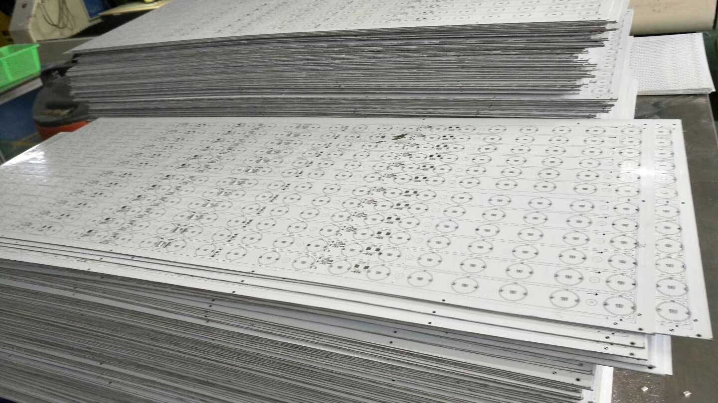
For guidance on selecting the overall material system, please refer toPCB MaterialsSection 1: Compare thermal conductivity, voltage resistance, and cost in a single table.
How to Choose the Right LED Aluminum Substrate
When selecting the appropriate LED aluminum substrate, the following factors should be considered:
- Power and operating temperature requirements for LEDs.
- PCB Dimensions and Shape.
- Heat dissipation requirements, including whether an additional heat sink is needed.
- Cost Budget.
Advanced: Five Key Considerations for SMT and the Assembly Process
Aluminum substrates differ significantly from standard FR-4 boards during the placement and assembly stages. The following five issues are the most common:
- The reflux curve needs to be recalibrated.: Aluminum substrates conduct heat quickly and have high thermal capacity, so the preheat section must provide more heat; otherwise, cold solder joints and poor solder joints are likely to occur;
- Stencils and Solder Paste: Aluminum substrates have good flatness but dissipate heat quickly; the selection of solder paste and the openings in the stencil must ensure an adequate amount of solder;
- Apply even torque to the screws.: Uneven force during radiator assembly can cause localized warping, subjecting the insulation layer to shear stress;
- An insulation withstand voltage test must be performed.: The finished product should undergo a withstand voltage test to verify that the insulation layer has not been damaged during machining;
- Choose the Right Board-Splitting Method: Aluminum substrates are typically separated using a router (milling) rather than a V-cut to prevent burrs and damage to the insulation layer.
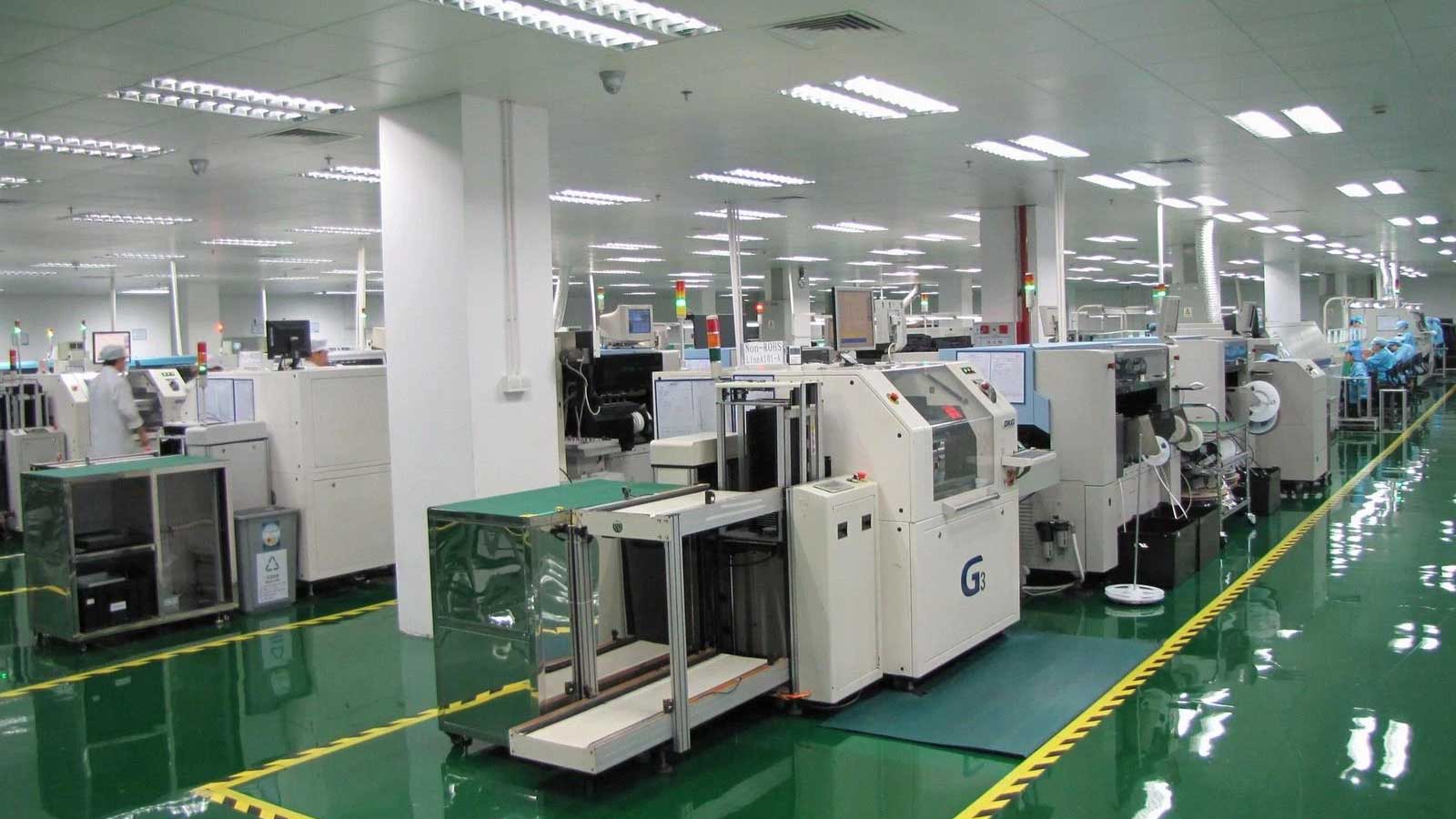
For an approach to troubleshooting welding defects, seeAnalysis of Causes and Solutions for PCB Soldering Defects; For details on solder paste and printing, seeKnowledge About Solder Paste for SMT Assembly。
Frequently Asked Questions
Question 1: Are LED aluminum substrates suitable for high-power LEDs?
Yes, LED aluminum substrates are suitable for high-power LEDs because they offer excellent heat dissipation, which effectively reduces the operating temperature of the LEDs.
Question 2: How do LED aluminum substrates differ from traditional FR4 PCBs?
LED aluminum substrates offer better thermal conductivity and mechanical durability, making them suitable for high-power LED applications, whereas traditional FR4 PCBs are typically used in low-power electronic devices.
Question 3: How do you mount LEDs onto an aluminum substrate?
LEDs can be mounted onto an aluminum substrate using surface-mount technology (SMT) and then soldered.
Question 4: Can aluminum substrates be used to make double-sided or multilayer boards?
Double-sided boards are possible, but multi-layer interconnects are limited. Because the aluminum substrate is conductive, plating through-holes can cause a short circuit with the base layer; therefore, special insulation treatment is required, or an alternative structure must be used. The standard practice is to use single-sided boards; when double-sided boards are needed, the process feasibility and cost must be evaluated.
Question 5: Is a thinner insulation layer always better?
No. Thinner materials can reduce thermal resistance, but this comes at the expense of voltage withstand capability and long-term reliability. The correct approach is to first determine the voltage withstand rating required for the product, and then—while ensuring that voltage withstand requirements are met—make the material as thin as possible and select a dielectric with a higher thermal conductivity.
Question 6: Can aluminum substrates be separated using V-Cut?
This is generally not recommended. V-cuts can cause stress concentrations and burrs on the aluminum substrate, which may damage the insulation layer. Aluminum substrates are more commonly formed using milling or stamping methods; this should be taken into account in advance when designing panel layouts.
Question 7: How can you determine if an aluminum substrate provides sufficient heat dissipation?
The most direct method is to measure the junction temperature or the device package temperature and then calculate the thermal resistance based on the values in the datasheet. Alternatively, during the prototype stage, you can use thermocouples to measure temperatures at multiple points to verify that the temperature rise at the hottest spot falls within the expected range, rather than relying solely on the parameters of the substrate material.
Question 8: What electrical tests are required for aluminum substrates?
At the very least, you mustInsulation Withstand Voltage Test(Typically 2–4 kV, as determined by the product’s safety standards) and continuity testing. If the product is subject to safety certification requirements, the voltage, duration, and pass/fail criteria for the withstand voltage test must be clearly specified in the specifications.
Question 9: How do I choose between a copper substrate and an aluminum substrate?
Copper has a higher thermal conductivity, but it is heavier, more expensive, and more difficult to process. Aluminum substrates are sufficient for most LED and power supply applications; copper substrates should only be considered when thermal resistance is a critical constraint and weight and cost are not major concerns.
Question 10: Why do the LEDs still burn out even when using an aluminum substrate?
Usually, it's not a problem with the substrate, but ratherA link in the thermal resistance chain has failed: Excessively high void rate in solder joints, uneven application of thermal interface material, poor contact with the heat sink, or drive current exceeding the design value. It is recommended to troubleshoot section by section along the thermal resistance chain, rather than simply increasing the thickness of the aluminum substrate.
Conclusion
Heat dissipation is one of the key challenges that LED manufacturers must address. Thanks to their excellent thermal conductivity and electrical insulation properties, aluminum substrates for LEDs have emerged as an effective solution to this problem. Selecting the right aluminum substrate can enhance the performance, reliability, and lifespan of LED products.
If you have any questions about LED aluminum substrates or other related topics, please feel free toContact Me. I will provide you with professional support.
Additional Information:The Role of LED Aluminum Substrates in Lighting Fixtures · Applications of 0-Ohm Resistors in Circuit Design
