

Throughout the production, storage, and operation and maintenance of electronic devices, the performance stability and service life of PCBA (printed circuit board assemblies) have always been a key focus of the industry.
Particularly in fields with extremely high reliability requirements—such as industrial control, medical equipment, and aerospace—the shelf life of PCBA directly affects the overall operational safety and cost control of the equipment.
Drawing on professional industry expertise and authoritative technical resources, this article presents a comprehensive and practical guide to PCBA preservation, covering topics such as the definition of shelf life, key influencing factors, strategies for extending shelf life, and analyses of common issues.
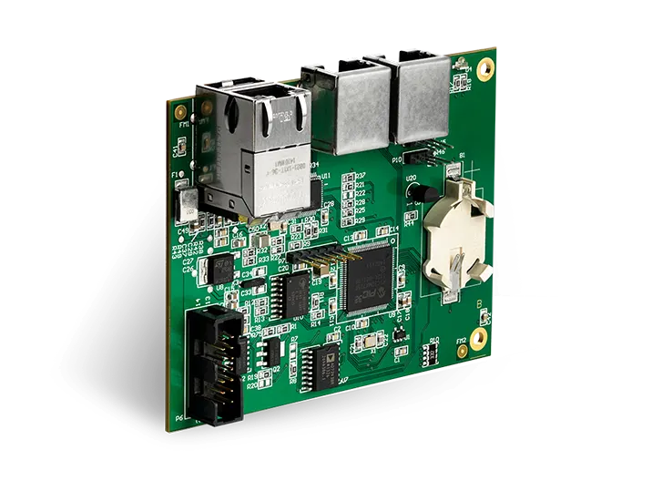
I. Key Definitions Regarding the Shelf Life of PCBA
The shelf life of a PCBA is not a fixed value, but rather a dynamic range influenced by multiple factors. According to industry practices and technical standards, under proper storage and usage conditions that comply with specifications,The shelf life of a PCBA is typically between 2 and 10 years.. This period encompasses both the static storage life of the PCBA when not in use and its dynamic service life under normal operating conditions. It is important to note that 2 years is typically the baseline warranty period (applicable to standard environments and standard component configurations), while 10 years represents the ideal maximum lifespan achievable under optimal conditions (such as strict environmental control, the use of high-reliability components, and scientific load management). Although a PCBA that has exceeded 10 years of service may still perform basic functions, the risk of performance degradation increases significantly; a decision on whether to continue using it should be made only after professional testing and evaluation.
II. Four Key Factors Affecting the Shelf Life of PCBA
The degradation of a PCBA’s lifespan is a complex physicochemical process. Its service life is primarily influenced by the following four major factors, which are interrelated and interact to directly determine the PCBA’s ultimate service life.
(1) Environmental Factors: “External Accelerators” of Life Span Decline”
The environment is the primary external factor affecting the shelf life of PCBA. Humidity, dust, temperature fluctuations, and corrosive gases can all accelerate the degradation of PCBA performance. The specific mechanisms of these effects and corresponding countermeasures are as follows:
- Effects of Humidity: When the relative humidity of the environment exceeds 60%, the metal plating on the surface of the PCBA (such as copper foil and pads) is prone to absorbing moisture from the air, leading to electrochemical corrosion (i.e., oxidation). Prolonged exposure to high humidity can lead to pad detachment and reduced circuit conductivity; in severe cases, it can even cause short-circuit failures. Data shows that in an environment with a relative humidity of 80%, the lifespan of a PCBA is reduced by more than 40% compared to an environment with a relative humidity of 40%–50%.
- Dust Hazards: Impurities such as industrial dust and fiber particles can adhere to the surface of PCBA boards, not only hindering heat dissipation (leading to localized temperature increases) but also potentially forming conductive pathways when the dust absorbs moisture, which can cause electrical leakage or short circuits. Particularly in dust-heavy environments such as electronics manufacturing facilities and mining equipment, the service life of a PCBA may be reduced to 1–3 years if no protective measures are taken.
- Temperature Fluctuations: Sudden changes in temperature can cause thermal stress differences between the PCBA substrate (such as FR-4 epoxy boards) and the components. For example, when the temperature rises abruptly from –20°C to 60°C, the differing coefficients of thermal expansion between the substrate and the components can cause solder joint cracking and component detachment. Long-term temperature fluctuations can gradually reduce the structural stability of the PCBA and shorten its service life.
- Corrosive gases: Corrosive gases commonly found in industrial environments, such as sulfur dioxide and hydrogen sulfide, react chemically with the metal plating on the surface of PCBA to form corrosive compounds (such as copper sulfide and copper sulfate). These compounds disrupt the electrical conductivity of the circuits, leading to increased contact resistance and ultimately causing equipment failure.
Based on the above factors,The recommended storage environment standards for PCBA are: Maintain a temperature of 23–25°C (±2°C) and a relative humidity of 40%–50%, while ensuring the environment is free of dust (cleanliness level meeting ISO 14644-1 Class 8 or higher), free of corrosive gases, and kept away from strong magnetic fields and sources of vibration. For long-term storage (over 1 year) of PCBA, it is recommended to use vacuum packaging with an internal desiccant (such as montmorillonite desiccant, with a moisture absorption rate of no less than 20%) to further isolate the components from environmental influences.
(2) Component Reliability: The “Intrinsic Core” of Lifespan Assurance”
A PCBA consists of various components, such as resistors, capacitors, inductors, and chips. The quality and reliability of these components directly determine the overall lifespan of the PCBA, and their impact is primarily reflected in the following areas:
- Component Materials and Manufacturing Processes: High-quality components are typically made from premium materials that are resistant to oxidation and high temperatures. For example, military-grade capacitors use tantalum metal casings with an oxidation resistance temperature of over 150°C, whereas standard civilian capacitors use aluminum casings with an oxidation resistance temperature of only about 85°C; In terms of soldering processes, components that use lead-free solder (such as Sn-Ag-Cu alloys) have solder joint reliability that is more than 30% higher than that of traditional leaded solder, and they also exhibit superior resistance to aging.
- Component Grades and Selection: There are significant differences in the design lifespans of components of different grades. Taking chips as an example, industrial-grade chips typically have an operating temperature range of –40°C to 85°C and a design lifespan of 100,000 hours (approximately 11 years); In contrast, consumer-grade chips have an operating temperature range of only 0°C to 70°C and a design life of 50,000 hours (approximately 5.7 years). If consumer-grade components are selected for industrial equipment, even if all other conditions are met, the service life of the PCBA will be limited by the component grade and is unlikely to meet expectations.
- Aging Characteristics of Electronic Components: Some components have an “intrinsic aging cycle”; for example, the electrolyte in electrolytic capacitors gradually evaporates over time, leading to a decrease in capacitance and an increase in leakage current. Generally, the lifespan of standard electrolytic capacitors (at rated temperature) is approximately 2,000–5,000 hours, while that of high-frequency, low-resistance electrolytic capacitors can be extended to over 10,000 hours. If a large number of standard electrolytic capacitors are used in a PCBA and it is exposed to high temperatures for an extended period, this will accelerate capacitor aging and consequently shorten the overall lifespan of the PCBA.
Therefore, during the PCBA design and production phases, priority should be given to selecting high-reliability components that meet project requirements (such as industrial-grade, automotive-grade, or military-grade components), and component quality should be ensured through supplier audits (such as ISO 9001 certification and AEC-Q100 certification). At the same time, when selecting components, their aging characteristics must be fully taken into account to prevent the entire PCBA from becoming scrap due to the failure of a single component.
(3) Printed Circuit Board (PCB) Materials and Surface Treatments: The “Fundamental Barrier” for Extended Service Life”
As the substrate for PCBA, although the material and surface treatment of a PCB do not directly cause lifespan issues, they indirectly affect the PCBA’s service life by influencing the circuit’s protective capabilities:
- Selecting PCB Substrates: Common PCB substrates include FR-4 (epoxy-glass fiber laminate) and CEM-1 (phenolic resin paper substrate), among others. FR-4 substrate offers good heat resistance (glass transition temperature, Tg, of approximately 130–180°C), moisture resistance, and mechanical strength. It is suitable for most industrial and consumer electronics applications and has a service life of over 10 years; In contrast, CEM-1 substrate has poor high-temperature resistance (Tg of approximately 100°C) and is prone to moisture absorption; it is only suitable for low-temperature, low-humidity environments, with a service life typically not exceeding 5 years. Therefore, for projects with high service life requirements, FR-4 or higher-grade substrates should be prioritized.
- PCB Surface Treatment Processes: The primary function of PCB surface treatment is to protect the copper foil circuits from oxidation and corrosion. Common processes include Hot Air Leveling (HASL), Electroless Nickel Immersion Gold (ENIG), Electroless Nickel Immersion Silver (ENIAg),OSP(Organic solderability preservative, etc.)—the protective effects vary significantly depending on the process:
-
- Hot Air Leveling (HASL): Lower cost, but with poorer surface flatness; solder pads are prone to tin whiskers; the risk of oxidation increases after long-term storage (more than 6 months); suitable for cost-sensitive applications with lower lifespan requirements.
-
- Electrolytic Nickel-in-Gold (ENIG): With high surface flatness, excellent oxidation resistance, a storage life of up to 1–2 years, and high soldering reliability, it is suitable for high-precision components (such as BGAs and QFPs) and PCBA requiring long-term storage.
-
- Silver Plating (ENIAg): Its antioxidant performance is second only to gold plating, and it is less expensive than gold plating, but it is prone to silver migration (in high-humidity environments). It is suitable for applications requiring a moderate service life (5–8 years).
-
- OSP (Organic Protective Flux): This method has the lowest cost and a simple process, but offers weak protection; its storage life typically does not exceed 3 months, and it is susceptible to environmental humidity. It is suitable only for PCBA that is assembled quickly after production.
In summary, if you need to extend the shelf life of a PCBA, we recommend selecting an FR-4 substrate combined with an immersion gold or immersion silver surface treatment. Additionally, take care to prevent scratches or contamination on the PCB surface during storage to ensure the integrity of the protective layer.
(4) PCBA Operating Load: The “Direct Cause” of Lifespan Depletion”
The operating load of a PCBA is the most critical factor affecting its dynamic service life. Operating under high loads accelerates the aging of circuits and components through heat dissipation, electrical stress, and other mechanisms. The specific effects are as follows:
- Current and Voltage Loads: When the operating current or voltage of a PCBA exceeds the rated values of the components, it causes the components to generate excessive heat. For example, the formula for power dissipation in a resistor is P = I²R. If the current exceeds the rated value by 20%, power dissipation will increase by 44%, causing the resistor’s temperature to rise significantly. Prolonged operation can lead to resistance drift or even burnout; For chips, excessively high voltage can cause the internal insulation to break down, resulting in permanent damage. Even if the load does not exceed the rated value, prolonged operation at peak load levels (such as 90% above the rated value) will accelerate component aging and shorten their service life.
- Operating Frequency: High-frequency operation causes a greater skin effect in the PCBA’s circuits (where current is concentrated on the surface of the conductor), leading to increased circuit losses and higher temperatures. At the same time, high-frequency signals place higher demands on component switching speed and immunity to interference. If components lack sufficient high-frequency performance, issues such as signal distortion and malfunctions may occur, and long-term operation can lead to component fatigue failure. For example, in a 500 MHz high-frequency circuit, the losses of a standard inductor are 3 to 5 times higher than in a 50 MHz circuit, and its lifespan is reduced by 30%–50%.
- Continuous operating time: The longer a PCBA operates continuously, the greater the cumulative wear and tear on its circuits and components. For example, a PCBA in industrial control equipment that operates 24 hours a day without interruption will have a service life approximately 60% shorter than that of a PCBA operating 8 hours a day. Long-term continuous operation also accelerates thermal aging of the PCB substrate and reduces its mechanical strength.
With regard to the impact of operational loads,The recommended strategies for extending service life are: During the PCBA design phase, optimize circuit parameters through circuit simulation (using software such as Altium Designer or Cadence) to keep operating current and voltage within 50%–70% (the mid-range) of the component’s rated values, thereby avoiding peak loads; For high-frequency circuits, select components with excellent high-frequency performance (such as high-frequency capacitors and high-speed chips) and optimize the layout (e.g., by shortening high-frequency signal line lengths and reducing the number of vias). During the operation and maintenance phase, plan operating times reasonably based on equipment usage requirements to avoid unnecessary continuous high-load operation. At the same time, regularly monitor the operating temperature of the PCBA (e.g., by using an infrared thermometer to check the temperature of critical components to ensure it does not exceed 80% of the rated temperature) to promptly detect and resolve overload issues.
III. Comprehensive Strategy for Extending the Shelf Life of PCBA
To ensure that PCBA units maintain excellent performance throughout their design life, it is necessary to establish a comprehensive quality assurance system covering the four stages of design, production, storage, and operations and maintenance. Specific measures are as follows:
(1) Design Phase: Laying the Foundation for Service Life
- Circuit Design Optimization: Reduces operational losses and risks through the use of redundant designs (such as dual backups for critical circuits), thermal management designs (such as adding heat sinks and optimizing PCB layout to reduce thermal concentration), and anti-interference designs (such as adding filter capacitors and implementing proper grounding).
- Component Selection Guidelines: Establish component selection criteria, specifying requirements such as component grade (e.g., industrial grade, automotive grade), temperature range, and lifespan parameters, and give priority to suppliers with a long-term, stable supply and a good reputation (e.g., TI, ADI, Murata, etc.).
- PCB Design Standards: Determine the PCB substrate (e.g., FR-4) and surface treatment process (e.g., electroless gold plating); optimize the PCB layout (e.g., avoid crossing traces, shorten the length of power traces); and ensure the PCB’s mechanical strength and thermal dissipation performance.
(2) Production Stage: Ensuring Quality Control
- Production Process Specifications: Production strictly adheres to IPC-A-610 (Acceptability Standard for Electronic Assemblies), controlling soldering temperature (e.g., 240–250°C for lead-free soldering) and soldering time (3–5 seconds) to prevent issues such as cold solder joints and missed solder joints; During the cleaning process, use environmentally friendly cleaning agents such as isopropyl alcohol to thoroughly remove flux residue from the PCB surface and prevent corrosion.
- Quality Inspection Process: Multiple inspection steps are incorporated into the production process, such as AOI (Automated Optical Inspection) to check solder joint quality, X-ray inspection to examine hidden solder joints such as those on BGAs, and ICT (In-Circuit Testing) to verify circuit continuity, ensuring that the production quality of every PCBA meets the standards.
(3) Storage Phase: Isolating Environmental Influences
- Packaging Protection: For PCBA units intended for use or held in reserve, use vacuum packaging (with anti-static shielding bags) that includes a desiccant and a humidity indicator card (replace the desiccant promptly when humidity exceeds 50%); for PCBA units stored in bulk, place them on anti-static shelves to prevent stacking and crushing.
- Storage Environment Monitoring: Install temperature and humidity sensors (with an accuracy of ±1°C and ±5% RH) in the storage warehouse to monitor environmental parameters in real time, and connect them to an alarm system (which triggers audible and visual alarms when temperature and humidity exceed the specified ranges); conduct regular (monthly) visual inspections of the stored PCBA assemblies to check for signs of oxidation or corrosion.
(4) Operations and Maintenance Phase: Dynamic Performance Assurance
- Load Management: Adjust the PCBA's operating parameters appropriately based on the actual operational requirements of the equipment to avoid prolonged operation under high loads; for example, set load threshold alarms in industrial equipment so that when the load exceeds the 80% rated value, the system automatically reduces the load or issues a warning.
- Regular Maintenance: Develop a PCBA maintenance plan that includes a comprehensive inspection every six months to one year, consisting of a visual inspection (checking for bulging or discoloration of components), parameter testing (using a multimeter and oscilloscope to measure voltage, current, and signal waveforms), and cleaning and maintenance (removing surface dust with compressed air and wiping with isopropyl alcohol as needed).
- Aging Management: For PCBAs that have been in use for more than 8 years (nearing the end of their service life), conduct aging tests (such as continuous operation for 72 hours at the rated temperature) to evaluate their performance stability; if significant performance degradation is detected (such as parameter drift exceeding 10%), replace them promptly with spare PCBAs to prevent equipment failure.
IV. PCBA Frequently Asked Questions (FAQ)
1. What is the recommended storage life for PCBA in different application scenarios?
The recommended shelf life of a PCBA should be determined based on the environmental and load conditions of the specific application:
- Consumer electronics (such as cell phones and home appliances): In a relatively controlled environment with low load, the recommended storage period is 3–5 years;
- Industrial Control (e.g., PLCs, variable-frequency drives): The environment may contain dust and experience temperature fluctuations, with moderate loads; the recommended shelf life is 5–8 years;
- Medical equipment (such as monitors and diagnostic devices): Requires extremely high reliability, strictly controlled environmental conditions, and a stable load; the recommended storage period is 8–10 years;
- Aerospace (e.g., satellites, drones): In harsh environments (such as high temperatures or radiation) with complex loads, military-grade components must be used; the recommended shelf life is 10 years or more (requiring periodic testing).
2. Can PCBA that has exceeded its shelf life still be used?
It is not recommended to use PCBA that has exceeded its shelf life directly; a decision should be made after evaluating it using the following steps:
- Visual Inspection: Inspect the PCB surface for oxidation, corrosion, or cracked solder joints, and check the components for bulging, discoloration, or detachment;
- Parameter Testing: Use specialized equipment to test the parameters of key components (such as chips, capacitors, and resistors) to verify that they fall within the rated range;
- Aging Test: Run continuously for 24–72 hours under rated conditions, monitor parameters such as temperature, voltage, and current on the PCBA, and check for any abnormalities;
- Environmental Adaptability Testing: Depending on the application scenario, conduct high- and low-temperature cycling, humidity testing, and other tests to evaluate the product’s environmental adaptability.
If all of the above tests are passed and performance meets operational requirements, the unit may continue to be used under enhanced monitoring; if any single test fails, the defective component or the entire PCBA must be replaced.
3. How can you quickly determine if a PCBA is nearing the end of its service life?
You can determine whether a PCBA is nearing the end of its service life by looking for the following four telltale signs:
- Performance Parameter Drift: Such as increased voltage output fluctuations, unstable current, and increased signal transmission delays that exceed the normal tolerance range;
- Abnormal Temperature Rise: The temperature of key components (such as chips and power modules) has risen by more than 10°C compared to normal operating conditions, with no significant change in load;
- Abnormal Appearance: Visible oxidation spots on the PCB surface, blackened solder joints, bulging components, fluid leakage (e.g., from electrolytic capacitors), and corroded leads;
- Increase in the Frequency of Malfunctions: The equipment experiences frequent crashes, reboots, and malfunctions, and the issues persist even after software-related causes have been ruled out.
When the above signs appear, the PCBA should be thoroughly inspected and maintained promptly to prevent sudden failures.
4. How can the service life of a PCBA be further extended in harsh environments (such as high temperatures and high humidity)?
In harsh environments, the following measures can be taken to extend the service life of PCBA:
- Environmental Isolation: Install a protective enclosure (such as a stainless steel or waterproof enclosure) around the PCBA and fill the interior with thermally conductive silicone gel or epoxy resin to isolate it from external moisture, dust, and corrosive gases;
- Active Cooling: Install a cooling fan, heat sink, or semiconductor cooler to keep the PCBA temperature at or below 70% of the component's rated temperature;
- Component Upgrade: Use components designed to withstand harsh environments, such as high-temperature capacitors (operating temperature range: –55°C to 125°C), waterproof connectors, and chips with corrosion-resistant coatings;
- Increased Frequency of Regular Maintenance: Shorten the maintenance cycle from six months to three months, increase the frequency of temperature and humidity monitoring as well as cleaning and maintenance, and promptly identify and resolve potential issues.
V. Conclusion
The shelf life of a PCBA is determined by a combination of factors across multiple stages—including design, production, storage, and operation and maintenance—and typically ranges from 2 to 10 years; however, its service life can be maximized through scientific control measures. In practical applications, it is essential to give full consideration to four key factors—environmental control, component selection, PCB manufacturing processes, and operational loads—and to establish a comprehensive quality assurance system. At the same time, regular testing and maintenance should be conducted to promptly identify and resolve potential issues. Only in this way can PCBA units be ensured to operate stably and continuously throughout their designed service life, providing a solid foundation for the reliability of electronic equipment. Whether in consumer electronics, industrial control, high-end medical devices, or the aerospace sector, the scientific management of PCBA lifespan will become a crucial factor in reducing costs and enhancing competitiveness.
