

This article will provide a detailed discussion of three aspects: right-angle traces, differential traces, and serpentine traces.PCB LayoutThree Special Routing Techniques.
I. Right-Angle Tracing
The impact of right-angle traces on signals is primarily reflected in three aspects.
1. Capacitive Load at the Corner
First, a corner can be treated as a capacitive load on a transmission line, which helps slow down the signal’s rise time and improve signal quality.
2. Impedance Discontinuities and Signal Reflections
Second, impedance discontinuities can cause signal reflections, which affect the stable transmission of signals. Therefore, in PCB design, it is important to avoid excessive right-angle turns, especially in high-speed circuits.
3. EMI Caused by Right-Angle Traces
Finally, it is worth noting the electromagnetic interference (EMI) issues caused by right-angle corners. In high-frequency, high-speed circuit design, even the smallest right-angle corners can become a key source of high-speed issues.
II. Differential Signaling
1. Advantages of Differential Signals
A differential trace is a pair of transmission lines carrying opposite signals, used to cancel out noise and improve signal quality. Differential signals offer the following advantages over single-ended signal traces:
- It has strong immunity to interference and can effectively cancel out common-mode noise.
- It effectively suppresses EMI and reduces electromagnetic radiation.
- It provides precise timing and is suitable for circuits with low-amplitude signals.
2. Key Considerations in Differential Signal Design
When designing differential traces, the following principles should be followed:
- Increase the spacing between parallel segments and reduce the coupling length to prevent signal crosstalk.
- Use differential traces with ribbon cables or buried microstrip lines to reduce transmission delay.
- For high-speed signal lines and those with strict timing requirements, avoid using serpentine routing.
III. Serpentine Line
1. The Need to Adjust the Delay
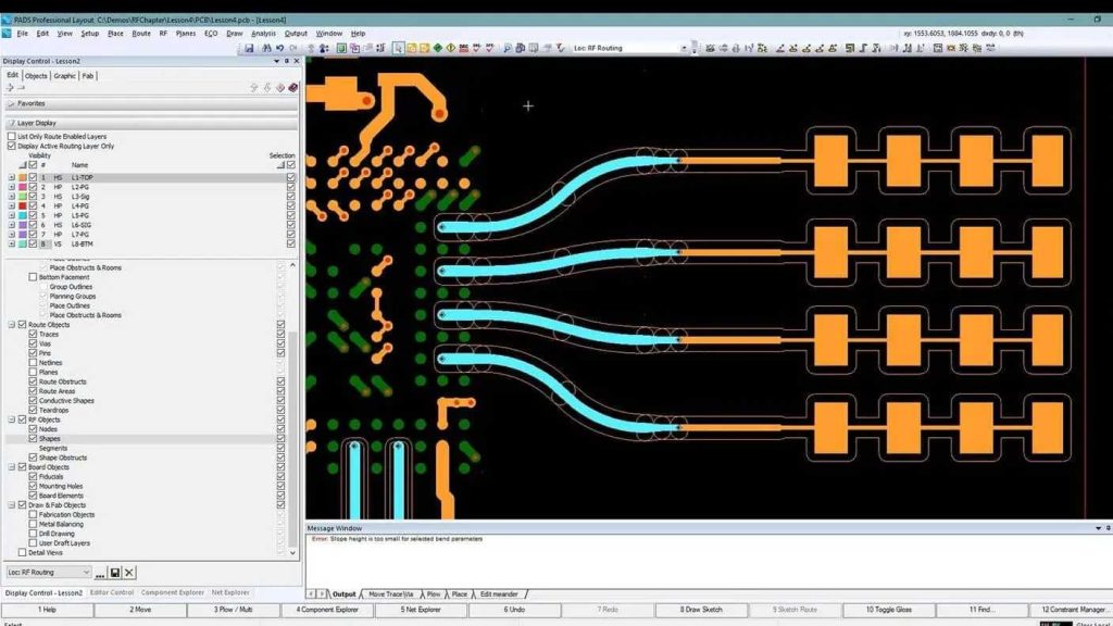
A serpentine trace is a routing method used to adjust the delay to meet system timing design requirements. Key parameters of a serpentine trace include the parallel coupling length (LP) and the coupling distance (s).
As signals travel along a serpentine trace, coupling occurs between parallel segments, creating a differential-mode signal. This can result in reduced transmission delay and degraded signal quality.
2. Recommendations for Handling Serpentine Wires
When working with serpentine traces, layout engineers can follow these recommendations:
- Increase the distance (S) between parallel line segments to at least 3H to minimize the coupling effect between the segments as much as possible.
- Reduce the coupling length (Lp) to prevent crosstalk saturation.
- Avoid routing traces in a zigzag pattern over a small area, especially for high-speed circuits.
- Snake-like routing at any angle can be used to reduce mutual coupling.
- In high-speed PCB design, serpentine traces are primarily used for timing matching and are not suitable for filtering or noise suppression.
By selecting and optimizing the routing strategies described above, PCB designers can better meet circuit performance and stability requirements, ensuring the reliability and performance of electronic devices.
In PCB design, routing strategies are a key factor; right-angle routing, differential routing, and serpentine routing each have their own applications and advantages. Choosing the appropriate routing strategy will help ensure the circuit’s performance and stability.
FAQs (Frequently Asked Questions)
What is a differential signal?
A differential signal is a pair of signals that have the same amplitude but are out of phase, used to improve signal quality and cancel out noise.
Why Should You Avoid Right-Angle Traces?
Right-angle traces can cause signal reflections and electromagnetic interference, which can affect circuit performance.
What is the role of serpentine traces in PCB design?
The serpentine line is used to adjust the delay to meet the system's timing design requirements.
How do you choose the right routing strategy?
The choice of routing strategy should be evaluated based on the specific circuit requirements and performance needs, following best practices.
What is the difference between differential signaling and single-ended signaling?
Differential traces use two opposite signals for transmission, while single-ended traces use only one signal line for transmission.
