

Metal Substrates Making Heat Dissipation Design a Reality
Processing of aluminum and copper substrates for LED lighting, power supplies, and power electronics. Evaluate suitable materials and laminates based on thermal load, dielectric strength, and assembly conditions.
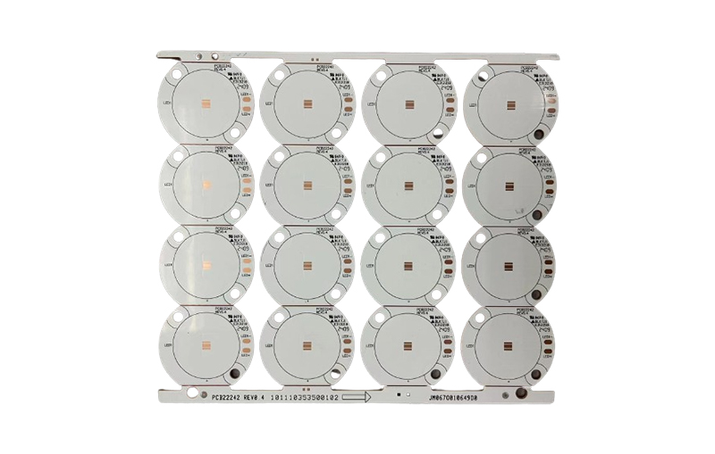
Aluminum-based / Copper-based · Materials and Structures Subject to Project Review
6 oz
Maximum Copper Thickness
3.0 mm
Maximum plate thickness
1.0–3.0 W/m·K
Thermal Conductivity Levels of the Dielectric Layer
The above represents the original processing capability range; the极限 parameters cannot be achieved simultaneously by default. Specific combinations are subject to engineering review.
01 / Material Selection
Aluminum-based or copper-based: Based on thermal requirements
First, confirm the location of the heat source, the allowable temperature rise, and the overall heat dissipation conditions; then compare the materials, weight, and manufacturing costs.
AL / Aluminum Substrate
Balancing Heat Dissipation, Weight, and Cost
Suitable for projects requiring large-area heat dissipation, such as LED light panels, automotive lights, and general power supplies.
Better suited to weight-reduction requirements; the molding method can be selected based on the part's shape and quantity.
Pay attention to the thickness of the dielectric layer, thermal conductivity, dielectric strength, and the installation contact surface.
CU / Copper Substrate
For More Concentrated Heat Loads
When heat is concentrated in a localized area and high thermal diffusion is required, copper-based solutions should be further evaluated.
Weight and material costs are typically higher, so the overall structure and manufacturing methods must be evaluated simultaneously.
The advantages of a copper substrate cannot replace the integrated design of the dielectric layer, interface materials, and heat sink.
02 / Thermal Design
In addition to thermal conductivity, you also need to consider the entire heat path.
The metal substrate consists of a copper trace layer, an insulating dielectric layer, and a metal base layer. Heat is transferred through the board and the mounting interface, ultimately dissipating into the enclosure or heat sink.
1.0 / 1.5 / 2.0 / 3.0 W/m·K refer to the nominal thermal conductivity values of the dielectric layer and do not represent the heat dissipation capacity of the entire PCB. The results are affected by the dielectric thickness, heat source area, interface contact, and external heat dissipation conditions.
The suitable power rating cannot be determined based solely on the thermal conductivity. Insulation breakdown voltage, temperature requirements, and reliability criteria should be verified in conjunction with the thermal design.
01
Copper Layer of the Circuit
Carries current and dissipates heat from the device into the surrounding area
02
Insulating Medium Layer
Provides both thermal conductivity and electrical insulation
03
Aluminum / Copper Substrate
Dissipate heat and integrate with the system's overall cooling structure
04
Interface Materials and Heat Sinks
Determines whether subsequent heat can be effectively dissipated
03 / Manufacturing Capabilities
Verify the parameters along with the actual stacking
Shenzhen Jingpeng Electronics evaluates manufacturability based on design specifications, material requirements, and order quantities. The following outlines the capabilities originally listed on this page; custom structures and parameter combinations require separate confirmation.
- Number of Floors / Structure
- Single-sided aluminum substrate, double-sided FR4 + copper-clad substrate
- Copper Thickness / Plate Thickness
- Maximum copper thickness: 6 oz; maximum board thickness: 3.0 mm
- Thermal Conductivity Levels of the Dielectric Layer
- 1.0 / 1.5 / 2.0 / 3.0 W/m·K
- Surface Treatment
- OSP, chemical gold plating, lead-free tin plating
- External Shaping
- Gong Shapes, V-Cuts, and Stamping Dies
- Sheet Dimensions
- Evaluated on a project-by-project basis; for oversized items, press-fitting and molding capabilities must be confirmed.
04 / Application Areas
Identify Key Review Points Based on Application Scenarios
01
LED Lighting and Automotive Headlights
Pay attention to the LED chip's heat conduction, dielectric strength, solder mask requirements for white LEDs, and installation flatness.
02
Switching Power Supplies and DC-DC Converters
Based on the power device layout, verify the copper thickness, current-carrying paths, insulation clearances, and heat dissipation contact surfaces.
03
Automotive Electronics
Evaluate temperature cycling, vibration, assembly tolerances, and operating environments based on specific components.
04
Motor Drives and Energy Storage
At the same time, evaluate high-current traces, creepage distances, dielectric strength, and local hotspots.
05
Power Electronics Modules
Select the structure based on the device packaging and heat flux distribution; avoid specifying the substrate solely based on the device type.
06
Special Heat Dissipation Structure
When composite laminates, special hole structures, or high-frequency signals are involved, conduct a materials and process review first.
05 / Preparing a Request for Quotation
Thorough Preparation of Materials Leads to More Effective Reviews
STEP 01
Manufacturing Documents
Gerber files, drill files, and outline files, specifying the stack-up, copper thickness, board thickness, surface finish, and quantity.
STEP 02
Thermal and Electrical Requirements
Device power dissipation, permissible temperature, dielectric strength, and contact conditions with the heat sink, air duct, or enclosure.
STEP 03
Assembly and Delivery Requirements
Mounting holes, tolerances, solder mask colors, inspection requirements, and desired delivery dates; if assembly is required, please include a separate BOM and coordinate file.
06 / Frequently Asked Questions
Metal Substrates: You May Also Want to Know
Can aluminum substrates be made into double-sided or multilayer boards?
A common structure is a single-sided aluminum substrate. Double-sided circuits or FR4-metal composite structures require an evaluation of lamination, interlayer connections, and insulation requirements; standard FR4 multilayer board processes cannot be directly applied.
Can through-holes be made in a metal substrate?
Holes involving electrical connections must be designed to prevent accidental electrical contact with the metal substrate. Whether this is feasible, how insulation should be implemented, and the corresponding tolerances must be evaluated on a case-by-case basis, taking into account the hole structure and the laminate configuration.
Does a higher thermal conductivity always mean better heat dissipation?
Not necessarily. Thermal conductivity is only one of the material specifications; the thickness of the medium, the area of the heat source, the interface material, and external heat dissipation conditions also affect thermal resistance. The selection must also meet insulation voltage withstand and reliability requirements.
When should you consider using a copper substrate?
When localized heat loads are concentrated and heat diffusion requirements are high, copper-based materials may be considered as a potential solution. Whether they are worth adopting should be determined by evaluating thermal analysis, weight, cost, and actual processing conditions.
Can a metal substrate replace a heat sink?
This cannot be assumed by default. While a metal substrate helps dissipate heat, the device as a whole still requires an effective heat dissipation path; whether an external heat sink is necessary should be determined through thermal design and actual testing.
How are lead times for prototypes and production runs determined?
Delivery times depend on material inventory, design complexity, surface treatment, and quantity. After submitting complete manufacturing specifications and your desired delivery date, Shenzhen Jingpeng Electronics will confirm a feasible production schedule.
Shenzhen Jingpeng Electronics
Aligning Materials, Manufacturing Processes, and Thermal Management Requirements
Please send us your design files and application requirements, and we will evaluate metal substrate options, manufacturing feasibility, and delivery arrangements based on this information.
