

Flexible PCB / FPC Reliable Connections Designed for Compact Spaces
For consumer electronics, battery connections, and precision assembly, evaluate materials, stack-up configurations, and manufacturing solutions for flexible printed circuits, taking into account space constraints, bending methods, and electrical requirements.
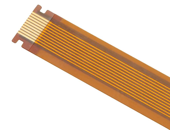
Flexible Printed Circuit Boards · Jingpeng Electronics Product Showcase
Floors 1–6
Range of Floors
PI / PET
Substrate Evaluation by Project
Static / Dynamic
Bending conditions to be confirmed separately
01 / Terms of Use
Just because something is flexible doesn't mean it can be bent an infinite number of times.
After assembly and forming, the position is relatively fixed.
Static Bending
Pay close attention to the installation space, bending angle, radius, and number of assembly operations to prevent creases or localized overloading during installation.
While the equipment was running, a repetitive motion occurred.
Dynamic Bending
Please provide the motion profile, bending frequency, target lifespan, and environmental conditions, and evaluate these in conjunction with laminate, copper foil, and sample testing.
Bend radius and service life cannot be guaranteed based solely on sheet thickness or the number of layers. Please provide the actual laminate configuration for the flexible area and the operating conditions, and ultimately verify them through appropriate testing.
02 / Manufacturing Capabilities
Identify the flexible zones and local structures, then confirm the parameters.
- Number of Floors
- Layers 1–6: To be reviewed based on specific layering and bending requirements
- Substrate
- Polyimide (PI), polyester (PET); material and assembly temperatures must be confirmed separately
- Panel Thickness Guidelines
- Original range: 0.05–0.8 mm; please specify whether this includes the adhesive layer, cover film, and reinforcement.
- Line Width / Line Spacing
- Original minimum reference: 0.05 / 0.05 mm, based on copper thickness and pattern review
- Drilling
- The minimum reference diameter for existing holes is 0.1 mm; finished hole dimensions, tolerances, and hole profiles are to be confirmed separately.
- Surface Treatment
- OSP, gold plating, tin plating, silver plating—select based on soldering or contact requirements
- Appearance and Dimensions
- Evaluated based on single panels, assembled panels, and processing methods; for large-size requests, please provide complete panel dimensions.
- Local Structure
- The areas of the cover film where windows are to be cut, reinforcements are to be added, connectors are to be placed, and folds are to be made must be indicated on the drawings.
The parameters listed above are for reference purposes only; it is not assumed that all limit values can be achieved simultaneously. The thickness of the flexible zone, the thickness after reinforcement, and the thickness of the rigid zone should be specified separately.
03 / Design Review
Consider bending, joining, and assembly together
01
Materials and Copper Foil
Specify the structure of the base film, copper thickness, adhesive layer, and cover film; select materials based on usage conditions; do not use “PI” alone to describe the complete multilayer structure.
02
Bend Area
Indicate the bending direction, radius, and no-trace areas on the drawings. The relationship between pads, vias, and thickness changes and the bending areas requires a special review.
03
Reinforcements and Connectors
Verify the reinforcement material, location, adhesive layer, and total thickness to ensure that the mating area matches the connector specifications and assembly method.
04
Form and Transition
Evaluate edges, grooves, and structural transitions to avoid localized stress concentrations; specific dimensions and tolerances are to be confirmed as shown in the drawings.
05
Electrical and Thermal Design
Evaluate based on current, copper thickness, trace dimensions, and allowable temperature rise; for high-speed traces, the stack-up and impedance requirements must also be specified.
06
Testing and Lifespan Validation
Requirements for electrical testing, dimensional measurements, visual inspection, and bending tests must be agreed upon prior to production. Passing electrical testing on bare boards does not substitute for actual motion life testing.
04 / Product Showcase
Use structural examples to communicate your needs
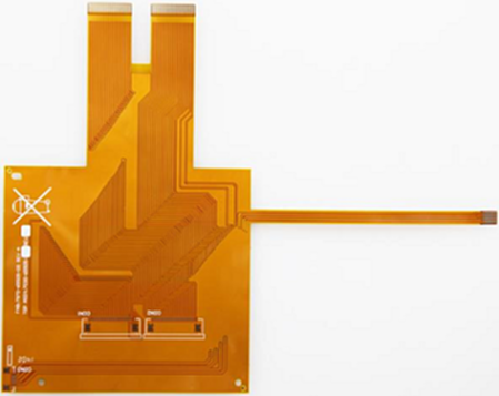
Six-layer FPC flexible circuit board
Multilayer structures must be evaluated by considering the stacking of flexible regions, interlayer connections, and actual bending methods.
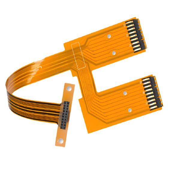
New Energy Lithium-Ion Batteries FPC
Based on the sampling or connection application, verify the current path, insulation, soldering, and assembly locations.

Large-Size, Thick-Copper, Double-Sided Flexible Circuit Boards
For large-size designs combined with thick copper, special attention must be paid to evaluating the outline, copper thickness, local structure, and bending conditions.
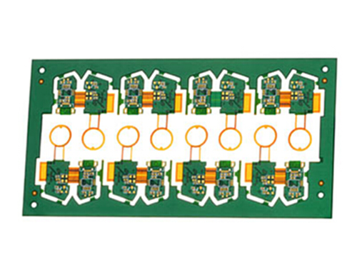
Bluetooth Headset FPC Flexible Circuit Board
For connections and assemblies in confined spaces, the flexible zones and locally reinforced zones must be clearly marked.
The images are for illustrative purposes only; the specific number of layers, thickness, surface treatment, and dimensions are subject to the finalized manufacturing drawings.
05 / Request for Quotation Materials
In addition to the Gerber files, the following structural information is required
01
Manufacturing Data
Gerber files, drilling, panel layouts, and lamination; specify materials, copper thickness, cover film, surface treatment, and quantity.
02
Mechanical Engineering and Assembly
Bend zones, direction, radius, reinforcement locations, and total thickness; if a butt joint is involved, provide the connector model or mating dimensions.
03
Use and Acceptance
Static or dynamic use, number of cycles, operating temperature range, acceptance criteria, and target date; for assembly requirements, please refer to the attached BOM and coordinate data.
06 / Frequently Asked Questions
FAQs on FPC Selection and Manufacturing
What is the difference between FPC and rigid-flex boards?
FPCs are primarily composed of flexible circuit structures and can incorporate localized reinforcements as needed for assembly; rigid-flex boards combine rigid and flexible circuit areas within a single structure. Simply adding a reinforcement plate does not equate to a rigid-flex circuit.
Are multilayer FPCs suitable for repetitive motion?
You cannot make that determination. Dynamic bending requires a comprehensive evaluation of the laminate structure, copper foil, thickness, bending radius, and movement patterns, as well as verification of the target service life; it cannot be determined based solely on the number of layers.
Are PI and PET direct substitutes for one another?
They cannot be used as substitutes by default. Since the materials and manufacturing processes differ, the suitability must be determined based on welding temperature, operating environment, dimensional stability, and joint configuration.
How should FPC thickness be labeled?
It is recommended to specify separately the total thickness of the flexible zone laminate, the structure of the cover film and adhesive layer, and the final thickness of the reinforcement zone. The mating dimensions of the connector should also be specified separately.
Can a cover film be used interchangeably with a standard solder mask?
These should not be considered interchangeable by default. The protective structure should be selected based on the material, window openings, bending, and assembly requirements, and the corresponding manufacturing process should be confirmed.
Can you provide a standard guarantee for the number of bends?
This cannot be specified without considering the specific conditions. The bending radius, angle, frequency, environmental conditions, fixtures, and failure criteria must be agreed upon, and then evaluated through testing of prototype samples.
How do I confirm the quote and delivery time for a prototype?
After submitting complete manufacturing and structural documentation, a review will be conducted based on materials, number of layers, reinforcement, external shaping, quantity, and inspection requirements to confirm the price and establish a feasible schedule.
Shenzhen Jingpeng Electronics
Adapt the layout to the space, and ensure the structure meets the functional requirements.
Send FPC drawings along with assembly and bending specifications to receive an evaluation of materials and manufacturing options.
