

In SMT assembly, selecting the appropriate component package is crucial. Component distributors typically offer components in a variety of packaging formats to accommodate different needs and placement loading preferences. These packaging options include bulk, tray, tubes, and batches, each with its own unique advantages; however, choosing the packaging type best suited for your project can be a challenge.
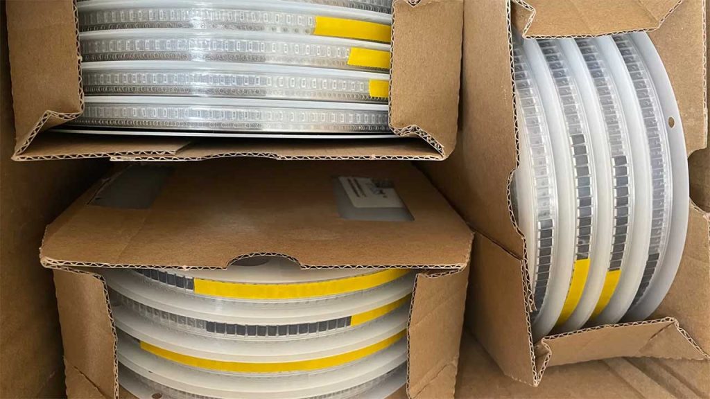
1. Panel Data and Batch Data
Bulk materials are typically transported in the form of tape reels, which are fed into a pick-and-place machine via a conveyor belt carrying components (usually small integrated circuits). However, the main difference lies in the length of the tape. Cut tape provides components in the form of small strips, whereas disc packaging material is long and continuous, with the components wrapped within it.
Although the final choice depends on the type of circuit board being assembled, in most cases, the tray data is better and more common.
The biggest advantage of tape reels is that they save time. Instead of loading 20 individual tapes, the operator simply loads the tape reel into the feeder for continuous feeding. In addition, quality standards require the operator to notify quality control (QC) personnel every time a new component is loaded into the machine. From an economic standpoint, this is a waste.
SMT tray information can also help operators avoid paper jams. Cut tape can sometimes get stuck in the feeder, whereas using rolls can often prevent jams. However, when a circuit board requires only a few specific types of components, cut tape is absolutely necessary. Therefore, it is very important to take this into account during the procurement phase.
2. Other Standard Packaging
Although cut-strip and reel packaging are typically the most common, there are other types of packaging available. Here is a brief overview of two additional packaging options to help you make an informed packaging decision for your specific production line.
3. Pallet Information
Trays are typically used for larger surface-mount packages, such as QFNs and BGAs. Trays experience less wear and tear because larger components are generally more expensive. Although fewer trays are typically used when shipping parts, they provide greater protection when transported via pipeline.
When purchasing SMT placement data, it’s important to remember that high-quality boards require high-quality data. In addition, you should pay attention to how the data is packaged when making a purchase.
Microstrip Transmission Lines in RF PCB Design
To date, microstrip transmission lines remain the most commonly used transmission line structure in RF and microwave design. However, as the speed and density of digital and mixed-signal designs have increased, the use of microstrip lines has gradually declined.
Structure
A microstrip transmission line consists of a conductor (typically copper) with a width of W and a thickness of t. The conductor is routed on a ground plane, which is typically wider than the transmission line itself and separated from it by a dielectric with a thickness of H. Best practice is to ensure that the ground reference plane extends at least 3H on both sides of the surface microstrip path.
Advantages
- Historically, the main advantage of microstrip lines may have been the ability to use only a two-layer board, with all components mounted on one side. This simplifies the manufacturing and assembly processes, making it the most cost-effective solution for RF circuit boards. Since all connections and components are on the same surface, through-holes are not required for connections. Aside from cost considerations, this is also ideal because the use of through-holes does not introduce additional capacitance or inductance.
- For the same impedance, microstrip lines are typically wider than ribbon lines. Since etching tolerances in manufacturing are absolute values, it is easier to more strictly control the characteristic impedance of the traces. If the trace width is 20 mils and the width is reduced by 1 mil through over-etching, this represents a very small percentage change. For example, according to FR408 data, with a dielectric constant of 3.8, a microstrip trace 20 mils above ground and 11.5 mils high will result in a characteristic impedance of approximately 50.8 ohms. If the trace width is reduced to 19 mils, the characteristic impedance will be approximately 52.6 ohms, representing an increase of 3.61 TP3T. Using the same data, a 5-mil microstrip line with 6-mil ground margins on both sides would yield approximately 50.35 ohms, but when the width is reduced from 1 mil to 4 mil, the characteristic impedance would be approximately 56.1 ohms—an increase of 11.51 TP3T. In some designs, the final characteristic impedance of the traces is not specified; instead, the final width is specified. Under the same over-etch scheme, reducing 5 million traces by 1 million mils will decrease the final trace width by 201 TP3T, while reducing 20 mils by 1 million mils will decrease the width by 51 TP3T.
Disadvantages
- Because microstrip transmission lines are typically quite wide and are routed on the surface of the circuit board, this reduces the surface area available for placing components. This makes microstrip lines virtually useless for high-density mixed-technology designs, where space is almost always at a premium.
- Microstrip transmission lines generate more radiation, which will be the primary contributor to the product's overall radiated EMI.
- As microstrip radiation increases, crosstalk becomes an issue. It is necessary to increase the spacing from other circuit components, which reduces the available routing density.
- Microstrip line designs typically require an external mask, which increases cost and complexity. The drive levels for many products are becoming smaller. This means the mask layer will be closer to the surface of the circuit board, which increases the capacitance at various points along the transmission line and thereby alters its impedance. Careful consideration is required when selecting microstrip transmission lines and output impedance models. If a trace needs to pass through the outer wall of the mask, it may be necessary to adjust the transmission line width over a short distance, typically through a “tunnel” that is positioned closer to the panel surface than the top of the mask.
- The characteristic impedance of microstrip lines may be affected by solder mask or other surface coatings. The application of these coatings can vary significantly from one SMT manufacturer to another—and even from one board to another from the same supplier—so the impact of these coatings on the impedance of surface microstrip lines remains unclear.
Selecting the correct SMT component package type is a critical part of ensuring a successful manufacturing and assembly process. Whether you are choosing panel or tray data, or deciding between microstrip transmission lines and other types of transmission lines, careful consideration is required to meet your specific needs and project requirements.
Frequently Asked Questions
1. What are bulk materials in SMT assembly?
Bulk materials for SMT assembly are typically supplied in the form of tape-and-reel packages, which contain components such as small integrated circuits; these components are picked and placed by a pick-and-place machine.
2. In SMT assembly, why are tape-and-reel components often preferred?
Roll-fed data is more popular because it improves production efficiency, saves time, reduces paper jams, and meets quality standards.
3. What are the applications of microstrip transmission lines in RF design?
Microstrip transmission lines are one of the most commonly used transmission line structures in RF and microwave design, offering advantages such as low cost and simplified manufacturing and assembly. However, they also have some limitations, such as being unsuitable for high-density hybrid technology designs.
4. What factors affect the characteristic impedance of a microstrip transmission line?
The characteristic impedance of a microstrip transmission line may be affected by solder mask or other surface coatings, and these factors may vary among different manufacturers or suppliers.
5. How important is it to select the appropriate component package in SMT assembly?
Selecting the appropriate component package is critical to ensuring the success of the manufacturing and assembly processes. Different package types are suited for different needs and projects, so careful selection is necessary.
