

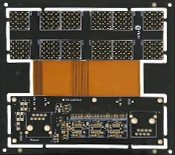
Flex-Rigid BoardsThe manufacturing process involves multiple steps and requires highly precise control and specialized equipment. The following is the basic process for manufacturing these types of boards:
- Rigid Circuit Board Design and Manufacturing: First, design and fabricate the rigid panel. Rigid panels are typically quite thick to provide a stable support structure. This step requires the use of depth-controlled milling to cut out windows, ensuring precision.
- Flexible Circuit Board Design and Manufacturing: Next, we’ll move on to manufacturing flexible circuit boards. These boards are typically thin and flexible and require specialized manufacturing equipment. When manufacturing flexible circuit boards, special attention must be paid to their dimensional stability, as the materials used are highly sensitive to temperature and humidity.
- Full-Panel Laminating of Flexible Boards with Cover Film: Flexible circuits are covered with a protective film, typically made of polyimide (PI). This helps protect the flexible circuit and ensures its stability.
- A Combination of Rigid and Flexible Boards: In this step, the rigid and flexible boards are assembled together to form a complex structure. This requires highly precise operations to ensure a proper fit between the two parts.
- Laminated PI Cover Film: The entire structure is pressed together, which requires specific parameters; for example, the pressure typically needs to reach 2.45 MPa. During the pressing process, it is important to ensure the surface is flat and to prevent the formation of air bubbles and voids.

Advanced: Three Conflicts That Make Rigid-Flex Boards Challenging to Manufacture
Rigid-flex boards are widely considered difficult to manufacture because they must simultaneously meet three sets of requirements that inherently conflict with one another:
- We need both rigidity and flexibility.: The rigid section must provide structural support and be suitable for soldering, while the flexible section must be able to withstand repeated bending; the material and thickness requirements for these two sections are exactly opposite;
- Press firmly and minimize excess adhesive.: Insufficient pressure can cause bubbles and voids, while excessive pressure can cause the adhesive to overflow into the flexible board area, directly affecting its bendability;
- Dimensions must remain stable, but materials expand and contract.: Flexible circuit board materials are highly sensitive to temperature and humidity; inconsistent expansion and contraction after lamination can directly cause alignment errors.
These three sets of conflicting factors determine that its process window is much narrower than that of ordinary boards, and they also explain why it imposes exceptionally strict requirements on equipment capabilities, process sequences, and environmental control.

For a basic definition and applications of rigid-flex boards, please refer toFlex-Rigid Boards与What Is a Rigid-Flex Board?。
Product Design Features of This Rigid-Flex Board
The design of this rigid-flex board has the following features:
- Structural Symmetry: The entire board has a symmetrical structure, which helps improve stability and circuit performance.
- Single-sheet flexible board: The flexible portion of a rigid-flex board is typically composed of a single flexible substrate, which ensures consistency in the flexible section.
- Full-Panel Laminating of Flexible Boards with Cover Film: To protect the flexible sections, the entire flexible board is covered with a protective film, typically made of polyimide (PI).
- Rigid core panel thickness ≥ 0.4 mm (total panel thickness ≥ 1.2 mm): The core of a rigid board has a certain thickness to ensure structural stability.
Advanced: Key Control Points for Each Step of the Five-Step Process
The five steps listed in the original text each have parameters that must be monitored:
| Steps | Critical Control Points | Common Failures |
|---|---|---|
| Rigid Circuit Board Design and Manufacturing | Controlling the precision of deep milling for window openings and the thickness of the core panel | The windows are opened to varying degrees, and residual adhesive is exposed. |
| Flexible Circuit Board Design and Manufacturing | Expansion and contraction stability; anti-jamming plate for the traction plate | Pallet Scrap, Dimensional Drift |
| Full-Panel Laminate | Alignment Accuracy, Quick-Press Parameters | Bubbles, Film Misalignment |
| Combination of Rigid and Flexible Boards | Alignment and Positioning Accuracy | Layer Misalignment, Displacement |
| Laminated PI Cover Film | Pressure of approximately 2.45 MPa, flatness | Bubbles, voids, delamination |
Three of these lessons are particularly worth remembering:
- Order is important: Typically, the flexible circuit board and the cover film are laminated first, followed by the fabrication of the rigid circuit board, so that their thermal expansion and contraction characteristics match;
- Don't skimp on the tow plate: Flexible boards are thin and flexible, so they are very prone to getting jammed when passing through equipment; using a pull board is the most effective way to feed them through;
- Quick Compression Parameters Are Key: You need to adjust the pressure, temperature, and time together; if you focus only on the pressure, you often won't get the dough to flatten properly.
For the requirements for flexible circuit board materials, seePerformance Requirements for FCCL in FPC Manufacturing; For the advantages and applications of flexible boards, seeGuide to the Advantages of FPC Applications。
Laminate Design for Rigid-Flex Boards
The stacking design of rigid-flex boards is critical, as it determines the board’s stability and circuit performance.
Advanced: A Readable Example of a Typical Stacked Structure
The original text notes in this section that a “diagram of a typical stacked structure design” has been inserted; here, we’ve included a table listing common symmetrical stacked structures to facilitate direct comparison with your design:
| Sequence | Materials | Function |
|---|---|---|
| 1 | Solder Mask / Cover Film | Outer Protection and Insulation |
| 2 | Copper foil on the outer layer of a rigid board | Device Side and Solder Side |
| 3 | Rigid Core Board (≥0.4 mm) | Provide structural support |
| 4 | NO-FLOW PP | Bond and prevent adhesive overflow |
| 5 | Flexible Circuit Board (PI Substrate + Copper Foil) | The main body of the bend zone |
| 6 | NO-FLOW PP | Symmetrical design to prevent adhesive overflow |
| 7 | Rigid Core Board (≥0.4 mm) | Symmetrical Support |
| 8 | Copper foil on the outer layer of a rigid board | Symmetrical Device Surface |
There are two strict rules that must be followed during the design process:
- The structure must be centrally symmetric., otherwise it will warp noticeably after being pressed;
- Adjacent layers in the flexible circuit area must use NO-FLOW PP., to prevent excess adhesive from entering the bend area and affecting flexibility.
In addition, there are three general constraints: the overall board thickness is typically ≥1.2 mm, and the rigid core layer is ≥0.4 mm; the more layers in the flexible section, the larger the required minimum bend radius; and components, vias, or overlapping cover films should not be placed within the bend area.

For details on material selection, seeWhat materials are used to make rigid-flex printed circuit boards?。
Here is an example of a typical stacked structure design:
(Insert a diagram of a typical stacked structure design)
Challenges During Production and Their Solutions
There are several technical challenges involved in manufacturing rigid-flex printed circuit boards, particularly during the production of the flexible and rigid layers. The following are some of these challenges and their solutions:
Flexible Circuit Board Section
Rigid PCB Manufacturing Equipment Used to Produce Flexible PCBs
Because flexible circuit board materials are thin and flexible, special equipment is required for their production. To ensure that the flexible circuit boards do not jam or become scrap, they must be processed using a pull-off board.
Laminated PI Cover Film
When laminating the PI cover film, special attention must be paid to the localized application of the film, and care must be taken to ensure that the rapid pressing parameters are set correctly. During rapid pressing, the pressure must reach 2.45 MPa to ensure the film is flat and firmly bonded, thereby preventing the formation of bubbles and voids.
Rigid Board Section
Window Cutouts in Rigid Core and PP
The key factors are the window cutouts in the rigid board core and the selection of PP material. Window cutouts in the rigid board are typically created using depth-controlled milling, while NO-FLOW PP should be selected to prevent excessive adhesive overflow during lamination.
Control of Expansion and Contraction During Laminating of Rigid-Flex Boards
Because flexible circuit materials have poor dimensional stability, the flexible circuit and the laminated PI cover film must be fabricated first, followed by the rigid circuit portion, to ensure that their coefficients of thermal expansion match.
Advanced: Five Challenges in Flexible Circuit Design and Their Solutions
| Challenges | Reason | Countermeasures |
|---|---|---|
| Pallet Disposal | Flexible circuit boards are thin and flexible, so they can easily get stuck when passing through equipment. | Using a traction belt to pull it through |
| Air bubbles in the cover film | Improper compression parameters or a dirty surface | Adjust the pressure, temperature, and time, and improve cleaning |
| Dimensional Drift | The material is sensitive to temperature and humidity | Control the environment and allow for compensation |
| Alignment Deviation | Expansion, Contraction, and Cumulative Positioning Errors | Make the flexible board first, then pair it with the rigid board. |
| Bending Fracture | Excessively small bend radius or improper selection of copper foil | Increase the radius and use rolled copper |
The execution sequence can be established by following these five steps:
- Set the scene first: Include temperature and humidity control requirements for flexible circuit segments in the work specifications;
- Make up for it later: Provide compensation coefficients based on historical expansion and contraction data;
- Rigid Backing Board: Use the actual dimensions of the flexible circuit board to align with the cutouts in the rigid circuit board;
- Full-Length Traction: All flexible circuit boards passing through the equipment must be equipped with a pull plate;
- First slice: Ensure that there are no air bubbles or voids at the bonded interface.
Advanced: Design of Bend Zones and Reliability Verification
The bend zone is the area where rigid-flex boards are most prone to problems; therefore, the following design guidelines must be followed:
- Bend Radius: Determine the minimum value based on the number of layers and copper thickness; generally, the higher the value, the more reliable it is;
- Trace Direction: The trace routing in the bend area should be perpendicular to the bend axis, and layer changes should be avoided in this area;
- Selecting Copper Foil: For dynamic bending, use rolled copper (RA); for static bending, electrolytic copper may be used;
- Coating Film Treatment: Stress relief must be provided at both ends of the bend to prevent stress concentration caused by an abrupt termination.
We recommend conducting at least four verification steps:
- Flex Life Test: Perform according to the actual bending angle and number of bends;
- Warmness and Damp-Heat: Verify that the interlayer bond strength is maintained;
- Slicing Inspection: Verify the quality of the bonded interface and the copper in the holes;
- Complete Unit Assembly Validation: Assemble and disassemble the unit once, following the actual assembly sequence.
Key Considerations for Prototyping Automotive Rigid-Flex Boards can be found atPoints to Consider When Prototyping Automotive Rigid-Flex Boards; For information on flexible board foundations, seeWhat Is an FPC (Flexible Printed Circuit)?。
Frequently Asked Questions
Question 1: What are the application areas for rigid-flex boards?
Answer 1: Rigid-flex boards are widely used in mobile devices, medical equipment, aerospace, and other fields. They are particularly useful in applications that require both stability and flexibility.
Question 2: What is the production lead time for rigid-flex boards?
Answer 2: The production cycle for rigid-flex boards varies by project. Typically, complex rigid-flex boards take several weeks or even months to complete.
Question 3: What should be kept in mind regarding the maintenance and care of rigid-flex boards?
Answer 3: To maintain and care for rigid-flex boards, avoid excessive bending and physical damage. Pay attention to temperature and humidity conditions during use to ensure their stability.
Question 4: What is the minimum number of layers for a rigid-flex board?
In theory, a single layer of flexible circuit board is sufficient, forming a three-layer structure when combined with the rigid boards on either side. In practice, four-, six-, and eight-layer designs are the most common; the number of layers depends on the routing density and whether a complete reference plane is required.
Question 5: How is the bend radius determined?
This depends on the number of layers in the flexible circuit board, the copper thickness, and whether the board will undergo dynamic bending. The more layers there are and the thicker the copper, the larger the required minimum bend radius. A common practice is to first select an initial value based on the number of layers, then verify and adjust it through bend life testing.
Question 6: Why is it necessary to use NO-FLOW PP?
Standard PP flows and overflows during lamination; if it overflows into the flexible section of the sheet, it causes that area to become hard and brittle, significantly reducing its flex life. NO-FLOW PP shows virtually no flow, effectively confining any overflow to the rigid section of the sheet.
Question 7: Is the pressing pressure of 2.45 MPa a fixed value?
No. This is a general guideline; the actual pressure must be adjusted based on plate thickness, the number of layers, the type of PP, and the equipment specifications. The primary goal is to flatten and compact the material without causing the adhesive to overflow, rather than mechanically applying a specific number.
Question 8: Why does the flexible circuit board section get jammed?
Because flexible circuit boards are thin and pliable, they lack rigidity and are prone to getting caught or jammed when passing through equipment rollers or conveyor sections. The most effective solution is to use a guide plate (lead plate) to ensure the flexible board passes through by having a “rigid board guide the flexible board.”
Question 9: What are the main factors contributing to the high cost of rigid-flex boards?
The main differences lie in the number of production steps, yield loss, and material costs. Compared to standard boards, it involves additional processes such as opening windows, laminating with a cover film, and multiple lamination steps. Additionally, the flexible board section is prone to scrap, and the materials used—such as PI and NO-FLOW PP—are relatively expensive.
Question 10: What should be confirmed most importantly during the proofing stage?
Three items:Is the bonded interface free of bubbles and voids?(Slice verification),Does the flex life meet the standard?(Tested),Is the assembly path unobstructed?(Assembly and disassembly of the entire unit). If these three items are approved, the risks during the mass production phase will be significantly reduced.
Conclusion
As a complex type of circuit board, rigid-flex boards combine the advantages of rigid and flexible boards and hold broad application prospects in the field of modern electronics. However, the manufacture of rigid-flex boards requires a high level of technical expertise and a deep understanding of the manufacturing process. Through proper design and meticulous fabrication, various challenges in production can be overcome, resulting in rigid-flex boards with stable and reliable performance.
Related Processes:Points to Consider When Prototyping Automotive Rigid-Flex Boards · What is a rigid-flex board?
