

Amid the rapid development of the electronics industry, technological progress has never ceased—but it should be a prudent one, or at least it should be. Before circuit boards are used in electronic products, they must undergo extensive testing to ensure they function as intended. And creating prototypes of circuit board designs is a crucial part of this process.
Advantages
1. Troubleshooting
By creating prototypes of your circuit board designs, you can identify potential issues before proceeding to full-scale production. This gives you the opportunity to document errors and determine which areas need improvement.
2. Savings in Time and Money
Prototyping can help you save time and money. If you identify issues early on, you can easily make adjustments to get the circuit board exactly the way you want it. You won’t have to worry about discovering problems after ordering a large batch of circuit boards and then having to start over.
3. Boost Confidence
Prototyping allows you to determine whether your design is effective before placing an order, which will boost your confidence. This not only makes the project easier to manage but also gives you confidence in your design.
Advanced: What Are the Four Key Things a Prototype Should Validate?
Prototyping isn’t just about “building a board to see if it lights up”; it validates four distinct types of objectives. You need to clarify these objectives first to determine which prototyping method to choose and how much to spend:
- Functional Validation: Does the circuit logic hold up? Are the components appropriately selected? Does the firmware run properly? At this stage, breadboards or development boards are acceptable; speed is the top priority.
- Electrical Performance Verification: Power supply ripple, signal integrity, EMI, power consumption, and temperature rise. These must be measured on actual boards that closely resemble the final stack-up and layout; the parasitic parameters of breadboards will yield completely incorrect results.
- Manufacturability Verification: Whether the packaging aligns correctly, whether the spacing is sufficient, and whether the stencil and the placement machine can handle it—these issues will only be revealed when a prototype is produced according to the formal process.
- Reliability Verification: Temperature cycling, vibration, aging, and drop testing. These tests are conducted during the pre-production phase; during the prototyping phase, only simplified preliminary tests are typically performed.
The benefits of separating these four categories are clear:Different prototypes with varying costs can be used at different stages...There's no need to invest in the most expensive prototype right from the start, nor should you base mass-production decisions on conclusions drawn from a breadboard prototype.

If you want to speed up the iteration cycle, you can refer toMethods for Speeding Up PCB Design Prototype IterationsThe method described there.
Disadvantages
1. Limitations on the Use of Breadboards
Although prototyping has many advantages, you may encounter some limitations if you use a breadboard to prototype your circuit board design. Breadboards are generally considered a relatively simple method, so they have a low learning curve, but they are also prone to problems.
2. The Challenges of Complex Design
If your design involves high voltages or highly complex circuits, using a breadboard is generally not a wise choice. These boards often cannot accurately represent the complex operations you are performing, which can lead to errors. Circuit design software, on the other hand, can identify and resolve these issues before the board is manufactured and tested.
3. Addressing High-Frequency Challenges
As modern circuit boards adopt surface-mount technology and require higher-frequency circuits, prototyping using breadboards can become challenging. Breadboards typically have high resistance, which can lead to stray capacitance that may affect the performance of the prototype.
Advanced: How to Choose Among the Three Prototyping Approaches
In real-world projects, there are three common approaches to prototyping, and there’s a huge difference in cost and what each can validate:
| Route | Cost | Cycle | Can be verified | Cannot verify |
|---|---|---|---|---|
| Bread Board / Perforated Board | Extremely low | That day | Functional Logic, Basic Device Operation | Electrical Performance, SI, EMI, Manufacturability |
| Development Board + Jumper Wires | 低 | 1–3 days | Features, Firmware, and Peripheral Interfaces | Performance and Structure in Real-World Deployments |
| Prototype Plate (Quick Plate) | 中 | 2–7 days | Electrical Performance, SI, Manufacturability, Structure | Long-term reliability (requires specialized testing) |
| Small-batch trial production | Higher | 1–3 weeks | All, including production line yield | —— |
When is it necessary to produce a physical prototype? There’s a very practical rule of thumb:As long as a circuit contains high-speed signals above tens of megahertz, Buck/Boost power supplies, RF components, or precision analog front ends, you should not draw conclusions based on breadboard experiments.. The distributed capacitance and contact resistance of the breadboard can mask the real problem and also create problems that do not actually exist.

For engineering details and common pitfalls in the prototyping phase, seePCB Prototyping Process and Precautions。
Using High-Quality Software for PCB Prototyping
Today, there are many software programs available for designing printed circuit boards. Although there are expensive options on the market, that doesn’t mean they’re the best choice. PCB design software is a free solution that helps you create prototypes and circuit board designs faster and more easily.
Packed with features
PCB design software offers a wide range of features, including controlled automatic routing, automatic component placement, monochrome grid options, optimal connection optimization, and multi-page schematics. These features allow you to test different designs and components to ensure that all functions on the circuit board work together and deliver the desired results.
Available for free
Although this PCB design software is available for free, it is by no means lacking in features. In fact, it is more powerful than some of its expensive competitors. It is a professional design software that offers free, real-time technical support.
Engineer Review
Once the circuit board design is complete, you can test it and even have it reviewed by an engineer for free to ensure it works properly. You can order several boards, or just one, to gradually assess its performance and make any necessary improvements.
Our goal is to simplify the PCB design process as much as possible to ensure the highest quality and fastest turnaround times for your PCBs. You no longer need to rely on traditional breadboards to create PCB prototypes. This is exactly what PCB manufacturers discuss when outlining the pros and cons of creating PCB design prototypes.
Advanced: Six Hurdles to Overcome on the Path from Prototype to Small-Batch Production
A successful prototype does not necessarily mean it can be mass-produced. The following six items represent the most common gaps between prototypes and mass production; we recommend reviewing them one by one:
- Packaging and Pads: Manual soldering may be acceptable during the prototype stage, but for mass production, the process must pass through the stencil and the placement machine; therefore, the pad dimensions, stencil apertures, and component packaging must all be re-verified.
- Device Availability: The model used for the prototype may not be available in bulk, so you should identify a sourceable model and at least one alternative during the prototyping phase.
- Test Points: Prototypes can be tested using flying probes, but mass production requires ICT or flying probe coverage; test points must be laid out in advance.
- Imposition and Process Margins: Small-sized boards require panelization; the placement of V-cuts or stamp holes can affect delamination stress and structural fit.
- DFM Review: Before mass production, have the PCB manufacturer conduct a manufacturability review to identify any issues with the minimum hole diameter, ring width, and line spacing.
- Documents and Versions: BOMs, coordinate files, stencil files, and revision records must be traceable to specific versions; otherwise, we’ll run into the same issues again in the second round.
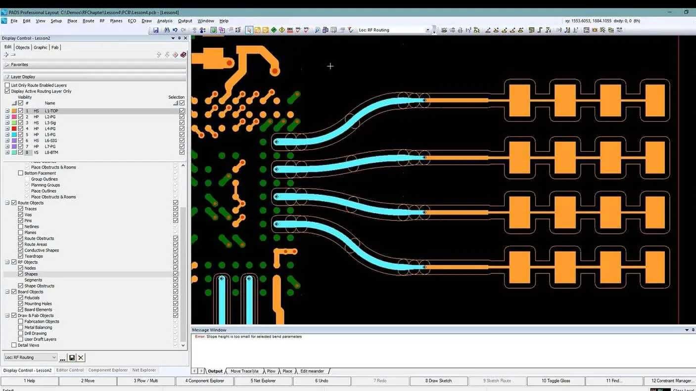
| Project | Prototyping Phase | Before mass production, it is essential to |
|---|---|---|
| Pads and Stencils | Manual soldering verification is sufficient. | Recalculate stencil apertures based on the placement machine's capabilities |
| Test Points | Jumpers or probes | ICT coverage meets the standard, and mounting holes are provided |
| Device | As long as it works, that's fine. | Lock in Delivery Lead Times and Alternative Models |
| Page Layout | Single-ply | Includes process margins, alignment holes, and panel-cutting methods |
| Document | Gerber and Screenshots | Complete BOM + Coordinates + Revision History |
Advanced: Four Ways to Control Prototype Costs and Timelines
The biggest waste during the prototyping phase is usually not the cost of the circuit boards, but ratherRework Cycles. The following four methods are the most effective in most projects:
- Perform a rule check before submitting to the board: ERC and DRC checks, along with packaging consistency checks, don't take much time but can catch most basic errors.
- Make an indeterminate circuit switchable: If the C-R-R value is 0Ω or it’s a dual-package device, a round of prototyping can help identify multiple viable solutions when you’re unsure about the parameters.
- Submit Multiple Variants at Once: It’s more cost-effective to split the disputed section into two smaller panels or divide it into sections on a single panel than to install three consecutive rounds of panels.
- Send the documents to the panel manufacturer in advance for preliminary review: Have the panel manufacturer define the process limits before officially starting production to avoid the situation where “we only realize it’s unfeasible after production has begun.”

There is also a checklist of rules to refer to during the layout phase:PCB Layout Design Specifications...which lists the general requirements for spacing, routing, and heat dissipation.
Conclusion
Creating a prototype of a PCB design is a critical step in ensuring that the circuit board functions properly before production. It offers many benefits, such as troubleshooting, saving time and money, and building confidence. Although there are some limitations to using breadboard prototypes, high-quality software can overcome these issues, making prototyping easier and more feasible.
Advanced: Five Steps for Acceptance Testing After Receiving the Prototype
Once you receive the board, don’t rush to power it up with all functions enabled. Follow the steps below to avoid most cases where you “think it’s working but it’s actually not”:
- Visual Perception and Connectivity: First, check for any obvious short circuits or open circuits, then measure the impedance between the power supply and ground to confirm there is no hard short circuit;
- Power-Up by Module: Power first, then signal; power up each stage sequentially while monitoring the current to prevent the chip from burning out immediately upon power-up;
- Key Waveforms: Measure the clock, reset, power supply ripple, and critical buses one by one, and compare the results with the design specifications;
- Boundary Conditions: Run tests for the upper and lower limits of the input voltage, as well as under full load and no load conditions, and at both high and low temperatures;
- Recording and Closed-Loop Management: Include the issues, causes, and changes in the revision log so that there is a record to refer to for the next round.
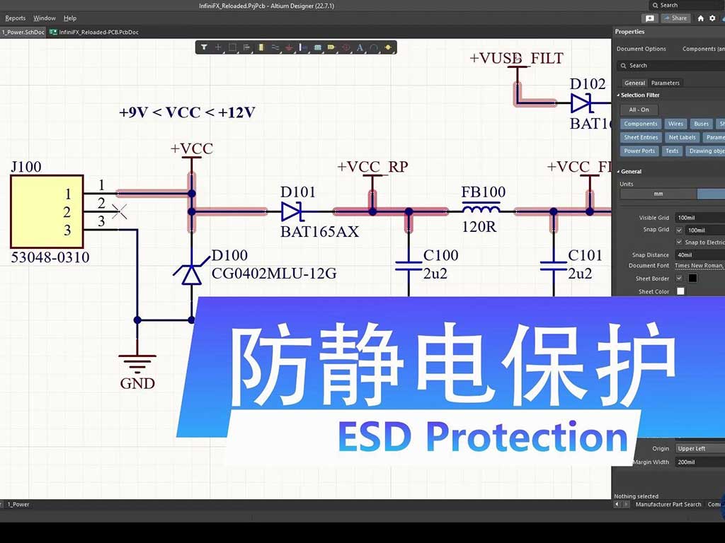
Electrostatic discharge (ESD) and protective design are most easily overlooked during the prototyping phase, yet they are often the root cause of failures in small-batch production. For comparison, seeElectrostatic Protection Design for PCBsLet's make up this class.
Frequently Asked Questions
1. Is PCB design software really free?
- Yes, the PCB design software is free to use and very powerful.
2. Can I make changes after the prototype is designed?
- Yes, once you've created a prototype of your circuit board design, you can easily make modifications and improvements.
3. What types of circuit designs is the breadboard prototype suitable for?
- Breadboard prototypes are typically suitable for simpler circuit designs and have a gentle learning curve.
4. Is PCB prototyping suitable for high-frequency circuits?
- When working with high-frequency circuits, PCB prototyping is often a more viable option because it can better accommodate these requirements.
5. Why is prototyping so important for PCB manufacturing?
- Prototyping helps identify problems, save time and money, and build confidence in the circuit board design, ensuring that it functions properly during the production phase.
6. Is the breadboard prototype completely useless?
No. It's inPure Functional Logic Verification and Educational DemonstrationsIt remains highly efficient: for just a few yuan and in a matter of minutes, you can verify whether a chip will function as expected. The problem is that you can’t use its results to assess electrical performance; whenever high-speed, power supply, or analog accuracy are involved, you must switch to a physical board.
7. How many sample pieces should be made at a time?
Generally3–5 piecesThis is a reasonable number. If there are fewer than 3, there won’t be enough to replace them if they’re damaged during soldering; if there are more than 5, the extra boards will be wasted if a design error is discovered in the first round. If there are uncertain parameter variants on the board, you can add more boards based on the number of variants.
8. If the prototype passes testing, can it go directly into mass production?
We do not recommend proceeding directly to mass production. Prototyping is used to verify whether the design is correct, while mass production requires verifying whether the production line can produce the product consistently. In between, there must be at least one round of DFM review, test point planning, and small-batch trial production to identify yield and supply issues.
9. Is the quality of prototype boards the same as that of mass-production boards?
Electrical performance and visual inspection standards are generally consistent, butKuai Ban may have a more flexible production window....and there are limited options for panel layout, process margins, and surface finishes. If reliability needs to be evaluated during the prototyping phase, it is recommended to explicitly require that prototypes be produced using mass-production processes.
10. Should impedance control be implemented during the prototyping phase?
This should be done whenever high-speed signals are present (typically with short rise times and rates of several hundred megahertz or higher). If impedance is not controlled in the prototype, the measured signal quality has no reference value and may actually mislead design decisions. For relevant standards, please refer to34 Common IPC Standards for Printed Circuit Boardsthe corresponding provisions in .
Related Processes:Electrical Safety Clearances · 5 Key Considerations for PCB Design
