

Reliable PCB testing methods are essential to ensure the quality and performance of printed circuit boards. This article will introduce two common methods of automated PCB testing to help you better understand this important field.
Needle Bed Test Method
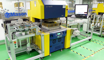
Needle Bed Test MethodThis is a common method for automatically testing printed circuit boards. It works by connecting spring-loaded probes to each test point on the circuit board. These spring-loaded probes apply a pressure of 100–200 grams to ensure good contact with the test points. This array of probes is referred to as a “probe bed.” Although this is an effective testing method, probe bed testers are expensive and difficult to maintain. Furthermore, the probe configuration must be selected based on the specific application, which adds to the engineering complexity.
Using Observation Instruments
Because circuit boards typically have compact and complex structures, it is necessary to use specialized inspection instruments for testing. Portable video microscopes are a common type of inspection instrument used to examine the microstructure of circuit boards. Through the video microscope camera, operators can clearly observe the details on the circuit board. This approach makes the design and inspection of circuit boards more intuitive and convenient. Today, many circuit board manufacturers use portable video microscopes, such as the MSA200 and VT101, to enable on-the-spot observation, real-time inspection, and group discussions—offering greater convenience than traditional microscopes.
Flying Probe Test
Flying Probe TestThis is an automated inspection method that does not rely on the pin pattern of fixtures or brackets. In this system, two or more probes are mounted on a tiny magnetic head that can move back and forth in the x-y plane, with test points controlled directly by CAD/Gerber data. The dual probes can move within a range of 4 mils from each other. Fly-probe testing is based on the principle of capacitance measurement, whereby the circuit board is pressed firmly against the insulating layer of a metal plate, which acts as the other plate of a capacitor. If a short circuit exists between the lines, the capacitance increases; if an open circuit exists, the capacitance decreases. This method can efficiently detect defects on circuit boards.
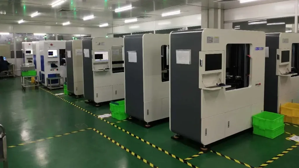
These are common methods for automated PCB inspection, and they all play a critical role in various applications. Choosing the appropriate inspection method depends on the PCB’s design, manufacturing requirements, and budget. Regardless of the method used, the quality and performance of the PCB can be reliably ensured.
Frequently Asked Questions
1. What is the needle bed test method?
The spring probe test method is an automated testing technique that connects to each test point on a circuit board using spring-loaded probes. These probes apply pressure via the springs to ensure good contact with the test points.
2. Why is it necessary to use measurement instruments to test circuit boards?
Printed circuit boards typically have minute and complex structures that require specialized observation instruments for inspection to ensure the quality and performance of their microstructures.
3. What is the principle behind flying-probe testing?
Fly-probe testing is based on the principle of capacitance measurement, detecting faults on a printed circuit board by measuring capacitance values. The printed circuit board is pressed against a metal plate to form a capacitor, and changes in the capacitance value reflect the state of the circuits.
