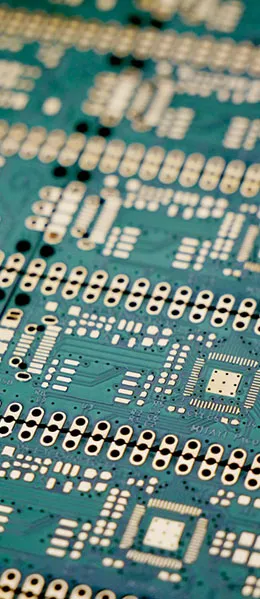
The manufacturing process for LED circuit boards involves a series of important steps, including soldering, self-inspection, peer inspection, cleaning, and polishing. These steps ensure the quality and performance of the LED circuit boards. In this article, we will provide a detailed overview of the basic steps involved in manufacturing LED circuit boards to help you better understand the process.

1. Soldering LED Circuit Boards
Soldering LED circuit boards is the first step in the manufacturing process, and it requires careful handling to ensure a good connection. The following are the key steps in the soldering process:
1.1 Determining the Direction of the Light
First, you need to determine the orientation of the LED. LEDs usually have a black rectangle; the side with the black rectangle is the negative terminal of the LED.
1.2 Orientation of the Circuit Board
Determine the orientation of the circuit board so that the front side is facing up, and locate the top-left corner of the two terminal blocks (inner and outer).
1.3 Determining the Direction of the Light on the Circuit Board
Starting with the LED in the upper-left corner, determine the positive and negative terminals of the LEDs in a clockwise direction. The typical sequence is negative-positive → positive-negative → negative-positive → positive-negative.
1.4 Welding
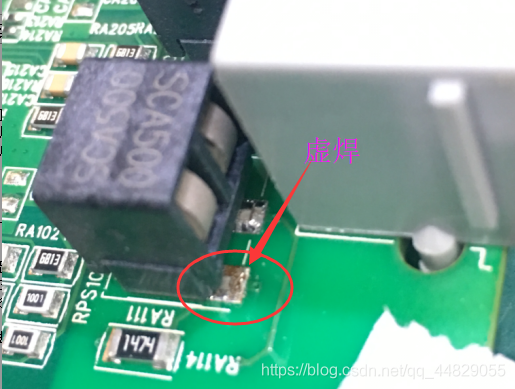
During the welding process, ensure that each weld is thorough and clean, with no cold welds or missed welds.
Advanced: How to Assess Solder Joint Quality—Cold Solder Joints, Missed Solder Joints, and Poor Solder Joints
The original text emphasizes “thorough, clean, and free of cold joints or missed welds” in both the welding and self-inspection steps, but on-site assessment requires more specific criteria. Common welding defects can be identified based on both visual appearance and electrical performance:
| Defects | Physical Characteristics | Electrical Performance | Processing |
|---|---|---|---|
| Cold solder joint | The solder joints are rough, dull, and grainy. | On and off—a light touch is all it takes to change it | Repair the solder joint; reapply solder |
| Missed Weld | Exposed pads, no solder mask | Fully Open Circuit | Repair Welding |
| Cold Welding | The solder has not melted completely and is irregular in shape. | High contact resistance | Reheat until completely melted |
| Lian Xi | Adjacent solder joints are connected by a solder bridge | Short Circuit | Desoldering Strip Cleaning |
| Solder balls | Small spherical tin beads are scattered across the board | Potential Short-Circuit Risk | Identify and Troubleshoot the Source |
There is a general consensus on what a qualified weld joint should look like:The solder completely wets the pad and the lead, forming a smooth, concave transition, and the lead’s outline is clearly visible.. If the solder joint bulges into a spherical shape, it indicates poor wetting; even if it is conductive at the moment, the connection is not reliable.
- Soldering Iron Temperature: Approximately 330–350 °C for leaded solder, and approximately 360–380 °C for lead-free solder;
- Exposure Time: Limit each soldering operation to 2–3 seconds; if it takes too long, it may damage the LED chip and the pad;
- Tinning Sequence: First, preheat the pad and the lead simultaneously, then feed the solder wire in from the other side;
- Post-Weld Inspection: Wait until the solder joints have completely solidified before moving the board to prevent cold solder joints.
- Visually inspect all solder joints once;
- Use a multimeter to check for continuity;
- Turn on the power to verify that all four LEDs light up simultaneously;
- Gently wiggle the component to make sure it isn't loose.
For an analysis of the causes of poor soldering, seeAnalysis of the Causes of Soldering Defects on Printed Circuit Boards; For the surface-mount process, seeSMT AssemblyProcessing Instructions.
2. LED Circuit Board Self-Test
After welding is complete, a self-inspection must be performed to ensure the quality of the welds and the continuity of the circuit.
2.1 Inspecting Solder Joints
First, check the solder joints for issues such as cold solder joints or missed solder joints.
2.2 Circuit Continuity Test
Use a multimeter to touch the positive and negative terminals on the circuit board (positive on the outside, negative on the inside) and check whether all four LEDs light up at the same time. Any circuit boards that fail this test must be modified until all of them function properly.
3. Cross-checking of LED Circuit Boards
After the self-inspection is complete, the LED circuit boards must undergo a peer inspection conducted by the person in charge to ensure quality.
Advanced: Why Clean?—The Long-Term Risks of Flux Residue
The original text calls for scrubbing with 95% alcohol. This step may seem simple, but it is actually intended to removeFlux Residue. During soldering, flux removes oxide layers and improves wetting; however, the residues left after soldering can cause three types of problems:
- Electrochemical Migration: When residues absorb moisture, they form ion channels, causing dendrites to grow between adjacent solder joints, which ultimately leads to electrical leakage or short circuits;
- Appearance and Reliability: Over time, residues absorb moisture and expand, which may cause the solder mask to bubble or peel;
- Obstacles in Subsequent Processes: Residue can affect the adhesion of the conformal coating and the quality of the dispensing.
The choice of cleaning agent depends on the type of flux.Rosin-based fluxYou can use alcohol or a specialized cleaning solution;No-Clean FluxIn principle, cleaning is not necessary, but if the product is used in an environment with high humidity or high voltage, cleaning is still recommended. Water-soluble flux must be rinsed off with deionized water.
- Dip a soft-bristled brush in the cleaning solution and brush in one direction to avoid pushing residue back into the gaps between the solder joints by moving the brush back and forth;
- Focus on scrubbing areas with dense solder joints and the undersides of IC pins;
- Use a clean, lint-free cloth to blot it dry; do not blow on it;
- Proceed to the next step only after confirming that there is no white powdery residue on the board surface.
One detail that's easy to overlook isIt must be thoroughly dried after cleaning.. Although alcohol evaporates quickly, liquid may still accumulate in the gaps between connectors on the board and beneath components; applying power before it is completely dry can also cause electrical leakage and corrosion.

For information on panel layout and panel separation methods, seeThe 9 Basic Steps of CAM Production; For key points on assembly and testing, seePCBA Testing。
4. Cleaning LED Circuit Boards
The next step is to clean the circuit board. Use 95% alcohol to wipe down the board, removing any residue and ensuring it remains clean.
5. Friction on LED Circuit Boards
This step involves removing each LED circuit board from the entire assembly one by one and using fine-grit sandpaper to smooth out any burrs along the edges of the circuit boards. This ensures that the circuit boards fit flush into their mounting brackets.
6. Cleaning LED Circuit Boards (Again)
Clean the circuit board with 95% alcohol to remove any dust left on it from friction.
7. Wiring the LED Circuit Board
Use a thin blue wire and a thin black wire to connect the circuit board. The connection point near the inner circle is negative; connect it to the black wire. The connection point near the outer circle is positive; connect it to the red wire. Make sure the wires run from the back to the front.
8. LED Circuit Board Self-Test (Again)
Inspect the connections to ensure that each wire passes through the pad; the length of the wire protruding from the pad on both sides should be as short as possible, and the wires should not break or come loose when gently pulled.
9. Cross-checking of LED Circuit Boards (Again)
Conduct another round of mutual inspections to ensure that quality meets the requirements.
Advanced: What Exactly Does "Seasoned" (Aged) Mean?
The original text specifies the burn-in conditions as 15 mA per LED for 8 hours. These figures were not chosen arbitrarily; they are based onEarly Failure ScreeningThe rationale: The failure rate curve for electronic products follows a bathtub shape, with a high failure rate in the early stages, followed by a stable period of random failures. The goal of product maturation is to ensure that early failures are detected before the product leaves the factory.
| Failure Modes | Typical Symptoms | Can experience be used to identify |
|---|---|---|
| Welding Defects | Flickers when turned on; some parts do not light up | Yes, it becomes apparent as soon as power is turned on. |
| Chip Defects | Rapid light decay, color shift | Yes, but it requires sufficient time. |
| Parameter Drift | Abnormal Increase in Current | Yes, through continuous monitoring |
| Material Aging | Failure after prolonged use | No, it's due to wear and tear. |
| Insufficient Design Margin | Failure in High-Temperature Environments | In some cases, stricter conditions are required. |
The principles for setting parameters are as follows:Slightly above normal operating conditions, but not high enough to introduce new failure mechanisms. Taking 15 mA as an example, if the LED’s rated operating current is 20 mA, then 15 mA corresponds to a 75% stress level, which both accelerates the detection of defects and prevents batch-wide damage caused by overheating.
- Current: Generally, 70%–90% of the rated value is used; refer to the device manual for specifics;
- Duration: 4–8 hours for consumer-grade products; up to 24–168 hours for industrial and automotive-grade products;
- Environment: Room temperature is sufficient; highly reliable products undergo additional high-temperature aging;
- Record: Measure the photometric parameters once before and once after aging, and compare the light decay and color coordinate drift.
- Before the test, record the initial brightness and forward voltage drop for each lamp;
- Apply power at the set current and perform periodic inspections;
- After completion, conduct a retest and remove any units with light decay exceeding the limit or that are defective;
- Record the failure distribution and provide feedback to the welding and incoming materials departments.
For thermal design considerations, seeHigh-Efficiency Heat Dissipation Solutions for Aluminum Substrates; For information on selecting metal substrates, seeMetal Substrate。
10. LED Circuit Board Maturation
The final step is to burn in the wires on the LED circuit board. As needed, apply power so that a current of 15 mA flows through each LED; the burn-in time is generally 8 hours.
These are the basic steps in the manufacturing of LED circuit boards; each step is crucial to ensuring the quality and performance of the final product. Through careful manufacturing and quality control, LED circuit boards can be widely used in various lighting and electronic devices.
Advanced: What Other Quality Control Measures Are Needed Beyond Self-Inspection and Peer Review?
The self-checks and peer reviews in the original text fall underManual Visual Inspection and Functional Verification...This approach is effective in small-batch, manual assembly scenarios, but it has clear limitations: it is difficult to sustain human attention for long periods, and defect detection relies on experience. To improve consistency, the following measures can be implemented at key workstations:
- Electrical Test Fixture: Use a probe or a spring-loaded pin to create a fixture, which allows for point-by-point measurements instead of using a multimeter, resulting in greater efficiency and consistency;
- Reference Sample Comparison: Compile a collection of actual photographs of acceptable welds and typical defects for inspectors to use as a reference;
- AOI Visual Inspection: Replaces manual visual inspection during mass production and has a high detection rate for solder bridges and missing components;
- First-Piece Approval System: Before starting each batch, produce a first-piece sample and keep a record of it to prevent batch-wide errors.
Quality control records are just as important.Record the welding parameters, number of defects, and failure modes for each batch....only then can you quickly pinpoint whether the issue stems from changes in personnel, equipment, materials, or methods when it reoccurs. For many small manufacturers, the root cause of quality fluctuations lies in the lack of traceable process data.
| Process Steps | Critical Control Points | Recorded Content |
|---|---|---|
| Welding | Soldering Iron Temperature, Soldering Time | Temperature Settings and Actual Measurements |
| Self-Check | Solder Joint Appearance, Lit Status | Number and Location of Defects |
| Cleaning | Cleaning Agent, Dryness Level | Cleaning Batches and Methods |
| Wiring | Polarity, Pull Force | Polarity-Confirmed Signature |
| Seasoned | Current, Duration, Luminous Decay | Comparison of Front and Rear Optical Parameters |
Frequently Asked Questions
What happens if the LED is connected with the polarity reversed?
LEDs are unidirectional conductors; when connected in reverse, they do not conduct current or emit light. While they generally do not fail immediately, if the reverse voltage exceeds the device’s allowable reverse voltage rating (approximately 5 V for most indicator-grade LEDs), permanent breakdown will occur. Therefore, the polarity must be verified at each connection point before wiring.
Why are two self-inspections and two mutual inspections required?
This is because defects are introduced gradually during the manufacturing process. The first self-inspection focuses on soldering, while the second focuses on wiring—the latter of which may pull on existing solder joints or leave wire ends exposed. By setting up inspection points after each critical process step, problems can be pinpointed within the smallest possible scope, rather than allowing them to accumulate until the very end.
What is the purpose of edge grinding and deburring?
After panel separation, glass fiber burrs and copper debris may remain on the edges of the boards. Burrs can prevent the boards from fitting smoothly into their mounting slots, affecting assembly dimensions; if copper debris falls onto the board surface, it may cause a short circuit. These can be removed by gently sanding with fine-grit sandpaper. Be sure to apply light pressure to avoid sanding away the solder mask or copper foil along the edges.
Can 95% alcohol be replaced with another cleaning agent?
Yes. The advantages of alcohol are that it evaporates quickly, leaves few residues, is compatible with most materials, and is inexpensive. Commercially available specialized electronic cleaning agents offer similar results, and certain formulations are even more effective at dissolving rosin residues. Be sure to avoid strong solvents that are corrosive to plastic components and screen-printed ink on the PCBA, such as acetone and white spirit.
Can the curing time be shortened?
It can be shortened, but the screening effectiveness will decrease. As a rule of thumb, the vast majority of welding-related defects become apparent within 30 minutes of power-on; therefore, a 2-hour test is sufficient for detecting welding defects alone. However, screening for chip light decay and parameter drift requires 8 hours or longer. Before shortening the test duration, the primary failure modes should be identified.
What is the appropriate production volume for manual soldering?
The threshold is typically set at several hundred units. The advantages of manual soldering include flexibility and extremely low startup costs, making it suitable for prototypes, small batches, and repairs; however, once production exceeds a certain volume, consistency becomes difficult to guarantee and labor costs rise rapidly, at which point it is advisable to switch toSMT AssemblyProduction line.
Why are aluminum substrates commonly used for LED circuit boards?
Both the luminous efficacy and lifespan of LEDs are sensitive to junction temperature; for every 10 °C increase in junction temperature, the lifespan is roughly halved. Aluminum substrates have a thermal conductivity far higher than that of conventional FR-4, allowing them to rapidly conduct heat from the chip to the heat sink, thereby controlling the junction temperature. High-power lighting, streetlights, and automotive headlights generally utilize metal substrate solutions.
How can I double-check the positive and negative terminals when connecting the wires?
In addition to the inner and outer ring rules mentioned in the original text, you can also use the diode setting on a multimeter to verify polarity: when the red probe is connected to the presumed positive terminal and the black probe to the negative terminal, the LED will glow faintly; if the connections are reversed, it will not light up. This is the most reliable verification method and is particularly suitable for boards with unclear polarity markings.
Additional Information:The 9 Basic Steps of CAM Production