

As customers' products continue to evolve toward smarter functionality, the requirements for PCB impedance are becoming increasingly stringent. This has driven Jingpeng Electronics to continuously refine its impedance design technology.
In this article, we will explore the factors that affect impedance and the common types of impedance to help you better understand the key points of high-frequency circuit design.
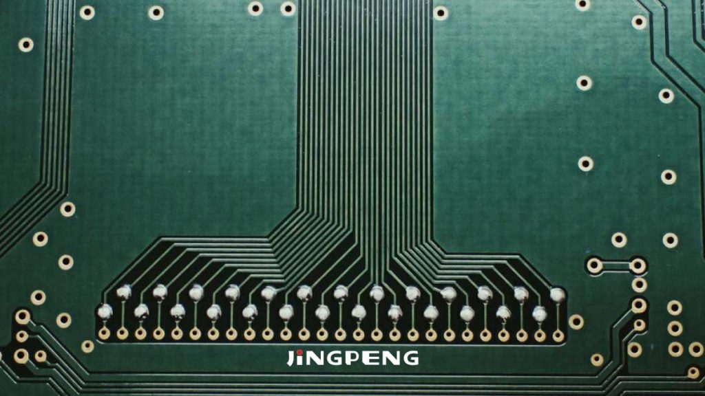
1. Definition of PCB Impedance
Impedance refers to the resistance encountered by high-frequency signals or electromagnetic waves as they propagate through the signal lines of an electronic device at a given frequency, relative to GND and VCC.
It represents the vector sum of various factors, including resistance, inductance, and capacitance.
2. Common Types of PCB Impedance
– Single-Ended Impedance
Single-ended impedance refers to the impedance value measured at a single signal line.
– Differential Impedance
Differential impedance refers to the impedance measured between two transmission lines of equal width and equal spacing during differential drive.
– Coplanar Impedance
Co-plane impedance refers to the impedance measured when a signal line transmits a signal between the GND and VCC planes surrounding it.
– Non-Coplanar Impedance
Dissimilar impedance refers to the impedance measured when a signal line transmits a signal between the GND and VCC connections surrounding it.
3. Factors Affecting PCB Impedance
Impedance is affected by a variety of factors, including the width (W) of the signal line, the thickness (T) of the conductor, the thickness (H) of the dielectric layer, and the dielectric constant (εr), among others.
Generally, impedance is inversely proportional to the dielectric constant, directly proportional to the thickness of the dielectric layer, inversely proportional to the line width, and inversely proportional to the copper thickness.
For example, line width is inversely proportional; you can adjust the line width to meet customer requirements. Similarly, the dielectric layer thickness is directly proportional; you can take the dielectric thickness of the PP film into account in the design.
Copper thickness is inversely proportional; the thickness of the inner and outer copper layers is related to the via copper thickness and must be calculated based on the substrate copper thickness and via copper thickness.
The dielectric constants are inversely proportional; this can be achieved by selecting a material with an appropriate dielectric constant.
4. Instruments for Measuring PCB Impedance
Currently, the primary instrument used for impedance testing is the Tektronix DSA8200. This instrument offers high measurement accuracy and a wide measurement range, making it suitable for impedance testing in high-frequency circuit design.
In high-frequency circuit design, a thorough understanding of impedance design techniques and the factors that influence them is crucial to ensuring circuit performance.
By carefully considering the points mentioned above, you can better meet your customers' requirements for high-frequency circuits and ensure outstanding product performance.
Frequently Asked Questions:
1. How can the impedance of a high-frequency circuit be reduced?
The impedance of high-frequency circuits can be reduced by adjusting the width of the signal lines, the thickness of the dielectric layers, and selecting appropriate circuit board materials.
2. What is differential impedance?
Differential impedance refers to the impedance measured across two transmission lines of equal width and equal spacing during differential drive; it is commonly used in differential signal transmission.
3. Why is the dielectric constant inversely proportional to impedance?
The higher the dielectric constant, the slower electromagnetic waves propagate through the dielectric, resulting in an increase in impedance. Therefore, the dielectric constant is inversely proportional to impedance.
4. What is coplanar impedance?
Common-plane impedance refers to the impedance measured when a signal line transmits between the GND and VCC planes surrounding it; it applies to specific PCB layout designs.
5. Why use the Tektronix DSA8200 instrument for impedance testing?
The Tektronix DSA8200 offers high precision and a wide measurement range, making it ideal for impedance testing in high-frequency circuit design and providing reliable measurement results.
