

Filters play a crucial role in electronic circuit design. PCB manufacturers frequently produce circuit boards for filters, and engineers pay close attention to the design rules for these filter boards, while also communicating with clients regarding their initial designs and offering recommendations. So, do you understand the principles and applications of filters in electronic design? Let’s take a closer look!
1. What Exactly Is a Filter? A Frequency-Domain Perspective
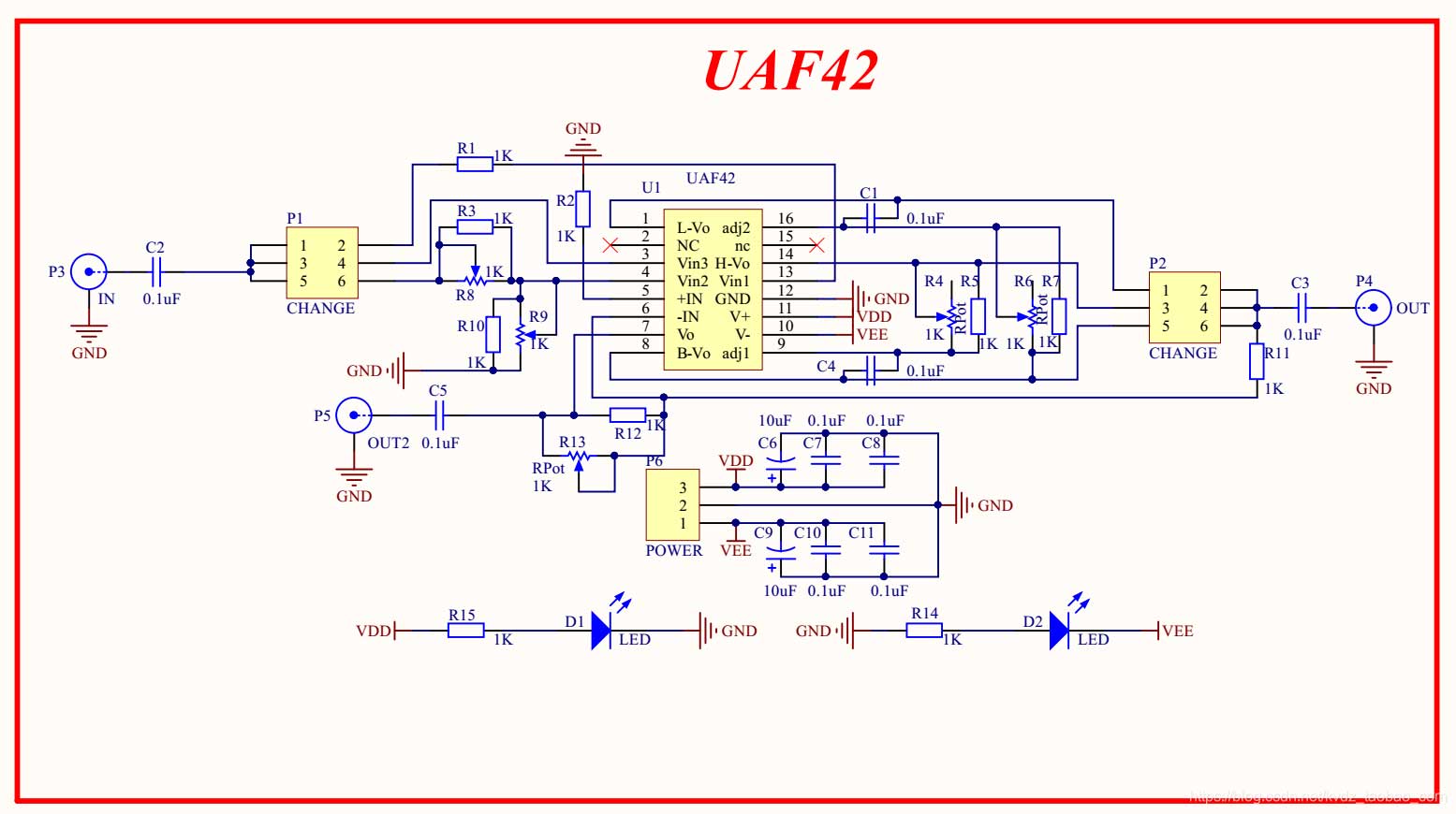
To understand filters, we must first accept a premise: signals in any real-world circuit are not pure sine waves of a single frequency, but rather a superposition of fundamental frequencies, harmonics, switching noise, and spatially coupled interference. Essentially, what a filter does isAssign different path impedances to different frequency components—Allow the desired frequency components to pass through with low loss, while reflecting the undesired frequency components back to the source or absorbing them and converting them into heat.
From an engineering perspective, the key metric describing this isInsertion Loss (IL), measured in dB. It is defined as the logarithm of the ratio of the power delivered to the load before and after the filter. A positive value indicates attenuation; the larger the value, the greater the attenuation. Several related parameters collectively determine whether a filter is adequate:
| Parameters | Physical Meaning | Reference for Typical Values | Key Considerations When Selecting a Model |
|---|---|---|---|
| Cutoff frequency fc | Frequency points at which insertion loss reaches -3 dB | RC low-pass filter: fc = 1/(2πRC) | A margin must be allowed for; component tolerances can cause fc to drift by more than ±10%. |
| Insertion Loss (IL) | The amount by which signals are attenuated in the stopband | First-order: 20 dB/decade; second-order: 40 dB/decade | For each additional order, the bandgap attenuation increases by 20 dB/decade. |
| Passband Ripple | Fluctuations in In-Band Gain | Butterworth 0 dB / Chebyshev 0.5–3 dB | Steepness Achieved Through Ripple: Use the Chebyshev Filter with Caution in Measurement Circuits |
| Quality Factor Q | Selectivity of Resonant Circuits | LC Bandpass: Q = f0/BW | The higher the Q, the narrower the bandwidth; however, component losses reduce the actual Q. |
| Blockband Suppression | Maximum attenuation achievable at a distance from the fc | Single-stage: 40–60 dB; Multi-stage: 80 dB+ | EMI certification scenarios often require a level of 60 dB or higher. |
An often-overlooked fact:Filters are not ideal devices.. Capacitors have an equivalent series inductance (ESL), and inductors have an equivalent parallel capacitance (EPC); at high frequencies, these cause the component characteristics to reverse—a 10 μF electrolytic capacitor ceases to behave as a capacitor at frequencies above 1 MHz. This is also why board-level filtering almost always involves ”connecting capacitors of different sizes in parallel” rather than ”using a single large capacitor to handle the entire load.”
2. The Function of Filters
Filters serve multiple purposes in electronic design; two of their primary functions are as follows:
- Separating the useful signal from the noise: Circuits are often subject to interference from various types of noise, which may originate from the power supply, other circuits, or the external environment. A key function of a filter is to separate this noise from the useful signal, ensuring that only the signal of interest enters the circuit.
- Improving the Accuracy of Signal Analysis: Certain applications require precise measurement or analysis of signals within a specific frequency range. Filters can suppress irrelevant frequency components, thereby improving the accuracy of signal analysis.
Applying these two principles at the board level gives rise to three additional categories of effects, which also occur frequently in real-world projects:
- Impedance Isolation: Insert an LC circuit between the switching power supply output and the downstream load to prevent dynamic load current from feeding noise back into the power supply loop.
- EMI Compliance: In conducted emission (CE) and radiated emission (RE) testing, the input filter network determines whether there is a 6 dB margin for passing certification.
- Anti-aliasing: Before sampling, the ADC must suppress components above the Nyquist frequency; otherwise, high-frequency noise will be aliased into the baseband and cannot be distinguished by software afterward.
Of these, aliasing suppression is the most commonly underestimated. Once aliasing occurs, it becomes completely impossible to separate the erroneous information from the true signal in the digital domain; therefore,Anti-aliasing filtering in the analog front end is the only part of the entire signal chain that cannot be corrected via software.. For related PCB design considerations, please refer toSignal Integrity Issues in PCB Design。
3. Classification of Filters
Based on the frequency bands and characteristics of the signals passing through them, filters can be classified into different types, which primarily include the following four:
- Low-Pass Filter: A low-pass filter allows the low-frequency and DC components of a signal to pass through while attenuating the high-frequency components.
- High-Pass Filter: A high-pass filter allows the high-frequency components of a signal to pass through while attenuating the low-frequency and DC components.
- Band-Pass Filter: A bandpass filter allows signals within a certain frequency range to pass through while attenuating signals below or above that range.
- Band-Stop Filter: A band-reject filter suppresses signals within a specific frequency band and allows signals outside that band to pass through.
In addition to classification by frequency response, there are three other classification criteria used in engineering, and it is often necessary to clearly specify all of them when selecting a model:
| Classification Dimensions | Main Types | Applicable Scenarios | Advantages | Limitations |
|---|---|---|---|---|
| By Implementation Device | Passive RC/LC, Active RC, Switching Capacitors | Power Supply Filtering, Signal Conditioning | Passive circuits are simple and reliable; active circuits can provide gain. | Bandwidth and Slew Rate Limitations of Active Operational Amplifiers |
| By the Approximation Function | Butworth, Chebyshev, Bessel, Elliptic | Measuring Instruments, Audio, Communications | Butworth is the flattest; the elliptic is the steepest | Elliptic filter with a notched band exhibiting rebound and group delay error |
| By Implementation Method | Analog Filters, Digital Filters | Front-End Conditioning / Back-End Algorithms | Digitally flexible and reconfigurable, with no temperature drift | Subject to constraints on sampling rate and bit depth |
| By Installation Level | Board-level, module-level (EMI filters), and connector filter arrays | System-Level EMC and Interface Protection | Good module-level consistency; certification has been obtained | High cost, takes up a lot of space |
4. Passive Filter Topologies: How to Choose Between RC, LC, π, and T Types
For the four most common passive topologies at the board level, the selection logic is actually quite straightforward—it depends on the relative sizes of the source impedance and load impedance:
- Single Capacitor (Bypass): Effective when the source impedance and load impedance are high. It has the lowest cost and is the most common method of power supply decoupling; be sure to place it close to the chip’s power pins.
- Single Inductor (Series Resistance): Effective when both the source impedance and load impedance are low. Commonly used to isolate digital and analog power domains.
- LC / L Type: The source side is higher than the load side. With a slope of 40 dB/decade, this is the primary topology used for DC-DC output filtering.
- π-type (C-L-C): High on both sides. Both the input and output have low-impedance bypasses, which provide the best ripple suppression for switching power supplies; however, care must be taken to avoid resonance with the power loop.
- T-type (L-C-L): Low on both sides. Suitable for applications where a low-impedance source drives a low-impedance load, such as isolating the output of a power amplifier.
There is a potential issue with π-type filters that must be verified: the CLC network and the power supply’s output impedance can form a resonant circuit, which may cause a problem at a certain intermediate frequency when the Q-factor is too high.Gain Peak...which actually amplifies the ripple. The engineering solution is to insert a resistor of a few tenths of an ohm in series with the capacitor branch, or to use tantalum or polymer capacitors with ESR for damping.
5. The Difference Between Line Filters and Frequency Filters
In electronic design, we often hear about line filters and frequency filters, which have different applications and operating principles.
Line FilterA line filter is a hardware circuit that typically operates before the ADC (analog-to-digital converter) takes a sample. It selectively filters out signals within a specific frequency range. For example, you can select 300 kHz, 1 MHz, or disable the low-pass filter. The purpose of a line filter is to remove high-frequency components and reduce the RMS value in the measurement results.
Digital FiltersThis is a software-implemented bandpass filter. When the digital filter is enabled, the corresponding analog filter is also activated to eliminate aliasing frequency components. Digital filters are typically used to process data acquired from an ADC and to perform further signal processing.
Frequency FilterIt typically does not affect the ADC sampling results but is used solely for frequency measurement and to generate the synchronization source required for calculations and the PLL source required for harmonic analysis. It is used to extract the fundamental frequency from signals with significant interference and distortion, and to generate more accurate synchronization and PLL sources, thereby improving measurement accuracy.
The division of labor among the three can be summed up in one sentence:”Line filter: Is the sampled input clean or not?” ”Digital filter: How is the sampled data processed?” ”Frequency filter: Is the measurement time reference accurate?”. Instruments such as power analyzers use all three because they address issues at three different levels, and none can replace the others.
6. PCB Implementation: Key Considerations for Implementing Filters on a PCB
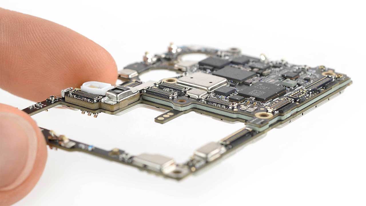
Just because the schematic is correct doesn't mean the filter will work. There are six potential points of failure at high frequencies during the board-level implementation stage:
- Loop Area of Decoupling Capacitors: The length of the trace from the capacitor to the chip's power pin is more important than the capacitance value. The larger the loop area, the greater the parasitic inductance, and high-frequency decoupling will fail. Prioritize placement directly adjacent to the pad.
- Ground-Loop and Impedance Coupling: When multiple filters share a common ground trace, crosstalk occurs through the common-ground impedance. The ground connections of the filters should be connected to a clean ground plane at a single point.
- Isolation Before and After the Filter: Parallel input and output traces can cause capacitive coupling across the filter, creating a ”filter bypass.” They must be physically separated in the layout and, if necessary, shielded with a ground plane.
- Minimizing High-Current Loops: The loop area formed by the inductor and capacitor in a power filter should be as small as possible; otherwise, the loop itself becomes a radiation source.
- Parasitic Effects of Vias and Pads: A 0.3 mm via has an inductance of approximately 0.5–1 nH, which becomes significant at frequencies above 100 MHz. The number of vias in high-frequency filter paths must be strictly controlled.
- Safety Clearance for Y Capacitors: For Y capacitors connected between the primary and secondary sides, the creepage distance and clearances on the PCB must comply with safety regulations; this requirement is frequently cited as grounds for rejection during inspections.
The stacked structure also has a direct impact on filtering performance; a fully flat surface minimizes the backflow path. For more information on this, seeThe Role of PCB Layer Stacking Design in Suppressing EMI, andEMI Design Specifications and Control Principles for PCBs。
7. Common Failure Modes and Countermeasures
The symptoms of filter malfunctions in the field are relatively consistent; by referring to the table below during troubleshooting, the issue can usually be pinpointed within half an hour:
| Failure Phenomena | Possible Causes | Positioning Methods | Countermeasures |
|---|---|---|---|
| The filtering performance in the high-frequency range is significantly inadequate. | The capacitor ESL plays a dominant role and becomes inductive once the frequency exceeds the self-resonant frequency. | Measuring the Z-f curve of a component using an impedance analyzer | Connect small-capacitance, low-ESL capacitors in parallel (e.g., 100 nF + 1 nF) |
| Adding a filter actually increased the noise. | The CLC resonance peak falls within the noise band. | Scan the frequency to check whether there are any spikes in the ripple spectrum | Connect a damping resistor or use a capacitor with ESR instead |
| Low-frequency attenuation does not meet the standard | Insufficient number of stages, or a drop in inductance due to inductor saturation | Measure the insertion loss again after increasing the current | Increase the number of stages / Use a desaturation inductor |
| The prototype passed, but the mass-produced units failed EMC testing. | Poor batch tolerances and layout consistency of filter components | Selected several prototypes for comparative testing | Tighten component tolerances, and define the layout and ground points |
| Performance Drift Following a Temperature Rise | Temperature-dependent drift in capacitance, increased core loss | Retest of High- and Low-Temperature Chambers | Select the C0G/NP0 dielectric and calculate the temperature rise of the core |
8. Filters supported by the PA5000 power analyzer from uZhou Ligong Zhiyuan Electronics
The PA5000 power analyzer, manufactured by Zhou Ligong Zhiyuan Electronics, supports a variety of filters, including:
- Analog line filters at 300 kHz and 1 MHz, as well as digital filters ranging from 100 Hz to 100 kHz. These filters are very useful in routine measurements; in particular, you can enable the line filters when you only want to obtain fundamental analysis results.
- Frequency filters set at 100 Hz, 500 Hz, 1 kHz, and 45 to 65 Hz (used in IEC harmonic mode). These frequency filters are used to improve measurement accuracy, particularly when determining the fundamental frequency of a signal with significant interference and distortion.
The design intent of this combination is clear: the line filter first suppresses out-of-band energy at the ADC input to prevent broadband noise from raising the RMS reading; the digital filter performs fine-tuning after sampling, with an equivalent bandwidth configurable from 100 Hz to 100 kHz as needed; the frequency filter operates independently of the measurement chain and is specifically designed to provide a stable PLL synchronization source for harmonic analysis. The bandwidth settings for these three components are independent of one another; in actual testing, they should be configured in the following order: ”line filter first, digital filter second, and frequency filter always enabled.”
9. Product Selection Process: Seven Steps from Requirements to Model Selection
Summarize the preceding content into actionable steps for selecting a product:
- ClarifyFrequency range to be covered与Frequency range to be suppressed, leaving a transition zone between the two sides.
- Determine the permissible values within the passbandMaximum Insertion Loss与Ripple。
- Requirements for Defining a BandgapMinimum Attenuation, and use this to determine the order of the filter.
- ConfirmSource Impedance and Load Impedance, select the corresponding topology (L / π / T).
- AccountingCurrent and Voltage Stress, particularly the saturation current of inductors and the voltage rating derating of capacitors.
- ConfirmTemperature Range, Safety Rating, Size Constraints。
- 在Impedance conditions closest to realityConduct actual testing, rather than relying solely on the ideal 50-Ω curve in the data sheet.
The final step is the most critical in practical applications. The insertion loss curves provided in data sheets are almost always measured in 50 Ω–50 Ω systems, whereas the source and load impedances in real circuits often deviate significantly from 50 Ω; it is common for the actual attenuation to differ from the values in the data sheet by 20–30 dB.
10. Conclusion
Filters are an indispensable component of electronic design; they help separate useful signals from noise and improve the accuracy of signal analysis. Understanding the different types of filters and their applications is a fundamental requirement for every electronics engineer. When selecting a filter, you need to consider the specific requirements of the application and the desired level of accuracy. By using filters appropriately, you can ensure that the performance and reliability of your circuit are maximized.
Frequently Asked Questions
1. What is the primary function of a filter?
The primary function of a filter is to separate useful signals from noise and improve the accuracy of signal analysis.
2. What are the different types of filters?
Filters can be classified into low-pass, high-pass, band-pass, and band-reject filters based on the frequency bands they allow to pass and their characteristics.
3. What is the difference between a line filter and a digital filter?
Line filters are hardware circuits that typically operate before the ADC samples the signal, whereas digital filters are implemented in software and are used to process the data acquired by the ADC.
4. What is the function of a frequency filter?
Frequency filters are used to extract the fundamental frequency of a signal, generate a synchronization source, and improve measurement accuracy.
5. What filters does the PA5000 power analyzer support?
The PA5000 power analyzer supports a variety of filters, including analog and digital filters, as well as frequency filters covering different frequency ranges, which can be selected based on application requirements.
6. Why doesn't the high-frequency noise go away even after connecting a large capacitor in parallel?
Because capacitors have equivalent series inductance (ESL), once the frequency exceeds the self-resonant frequency, they no longer behave as capacitors but as inductors, and their impedance increases as the frequency rises. The solution is to connect a small-capacitance, low-ESL capacitor in parallel (for example, a 10 μF capacitor in parallel with a 100 nF capacitor, which is then in parallel with a 1 nF capacitor), so that each capacitor handles a specific frequency range.
7. Is a higher-order filter always better?
No. For each additional order, the stopband attenuation increases by 20 dB/decade, but at the same time, the number of components, cost, size, passband insertion loss, and group delay distortion all increase. The standard engineering practice is to first use simulation to determine the minimum order that meets the specifications, and then add one order as a margin.
8. Why does adding a filter actually increase the noise?
Typically, an LC or CLC network forms a high-Q resonance with the power supply output impedance, resulting in a gain peak at a certain intermediate frequency. This can be mitigated by inserting a resistor of a few tenths of an ohm in series with the capacitive branch to provide damping, or by using polymer capacitors with a certain amount of ESR.
9. 板级滤波与模块级 EMI 滤波器如何选择?
板级方案成本低、体积小,但一致性依赖 PCB 布局与元件批次,量产 EMC 风险较高;模块级滤波器已通过认证、性能一致性好,但成本和占位大。小批量或认证时间紧的项目优先模块级,量大且 EMC 余量充足时优先板级。
10. 抗混叠滤波能不能用软件替代?
不能。混叠发生在采样那一刻,高频分量一旦折叠进基带,在数字域就与真实信号无法区分。抗混叠必须在 ADC 之前用模拟滤波器完成,这是整条信号链里唯一无法靠软件补救的环节。
Additional Information:Applications of 0-Ohm Resistors in Circuit Design · RF PCB设计中的平衡非平衡转换器
