

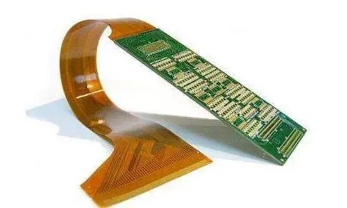
FPCFlexible Printed Circuit Boards(Flexible Printed Circuit) is a technology widely used in the electronics industry, offering unique characteristics and application advantages. This article will take an in-depth look at the three main characteristics of FPCs: flexibility, reliability, and cost-effectiveness.
1. Structural Analysis of FPCs: Three Layers or Five Layers
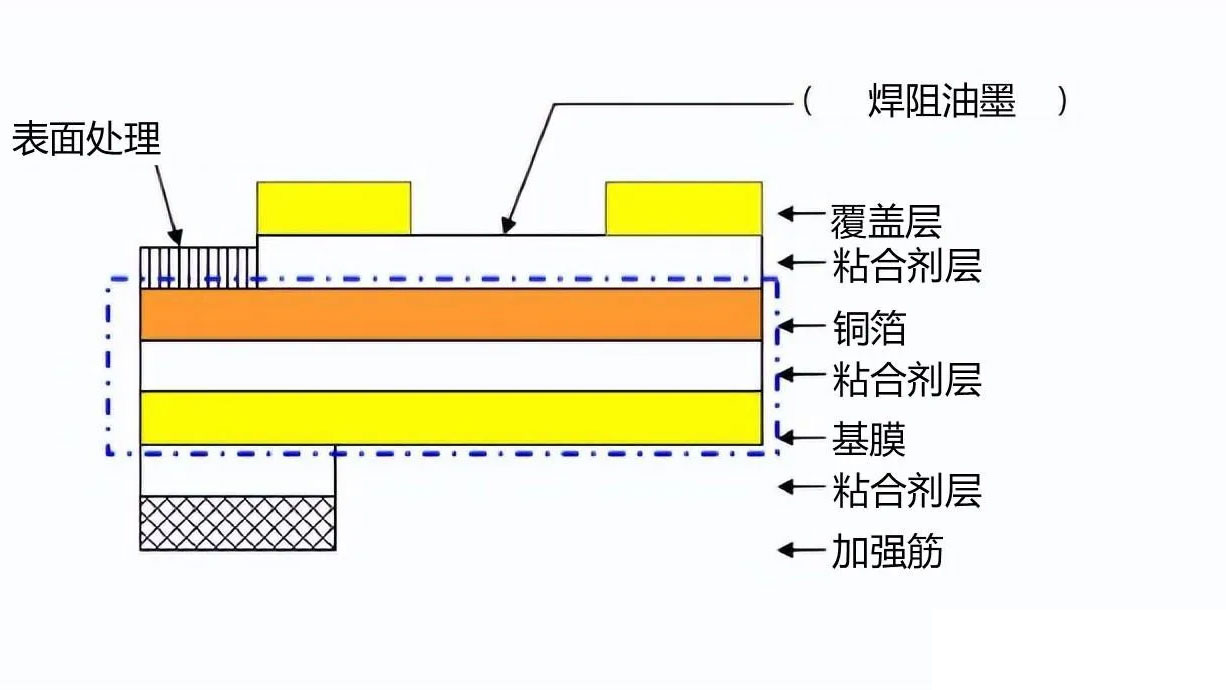
Before discussing the characteristics, let’s first clarify the physical structure of an FPC, since all of the characteristics discussed later stem from this structure. A typical single-sided FPC consists of five layers stacked on top of each other:
- Flexible Insulating Base Film: The most commonly used material is polyimide (PI), available in three thicknesses—12.5, 25, and 50 μm—which determine temperature resistance and flex life.
- Adhesive Layer (Adhesive): A layer that bonds the copper foil to the base film; typically an epoxy or acrylic system, with a thickness of 12–25 μm.
- Copper Foil Conductor: Rolled copper (RA) or electrolytic copper (ED); rolled copper must be used for dynamic bending applications.
- Coverlay: PI film + adhesive layer, which serves as a solder mask and provides protection; the pads are exposed at the cutouts.
- Stiffener: Apply PI, FR-4, or steel sheets locally to the connector insertion/removal area and the component soldering area.
In the industry, substrates are classified based on ”whether or not they have an adhesive layer” asThree-Layer Method (3L-FCCL, with adhesive)与Two-Layer Method (2L-FCCL, Adhesive-Free). The latter method involves casting or plating copper foil directly onto a PI film, resulting in thinner layers, higher temperature resistance, and better dimensional stability, but at a cost 30–60% higher. When creating high-density, fine circuits or when multiple reflow cycles are required, the two-layer method is the only option.
2. Key Characteristics of FPC Flexible Printed Circuit Boards
2.1 Flexibility and Reliability
The flexibility of FPC (flexible printed circuit) boards is one of their most notable features. They can be freely bent and folded as needed to adapt to spaces of various shapes and sizes, offering exceptional flexibility in design and application.
2.2 Cost-Effectiveness
The cost-effectiveness of FPC flexible printed circuit boards depends on several factors, including the complexity of the circuit design, the overall volume, and specific electrical or mechanical performance requirements. For relatively simple, small-sized circuit designs with moderate space constraints, traditional rigid circuit boards are often more cost-effective. However, for complex circuits, applications involving multiple signals, or those requiring specific electrical or mechanical properties, FPC flexible circuit boards may be the better choice.
2.3 Costs
The cost of FPC flexible printed circuit boards is influenced by a variety of factors. First, material costs are one of the primary factors. Prices vary significantly among different materials; the raw material cost of high-performance polyimide flexible printed circuits can be four times or more that of rigid printed circuits. The characteristics of flexible materials also make them difficult to process using automated methods, leading to lower production yields and an increased likelihood of defects during assembly.
3. Five Structural Types of FPCs and Selection Guide
The following are some of the main types of FPC flexible printed circuit boards:
3.1 Single-Sided Flexible Circuit Boards
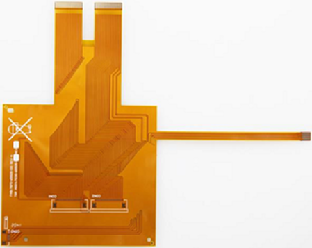
Single-sided flexible circuits are less expensive and are suitable for applications with modest electrical performance requirements. They typically feature a chemically etched conductive pattern, with the conductive layer located on one side of the flexible insulating substrate. The insulating substrate can be made of a variety of materials, such as polyimide, polyethylene terephthalate, aramid fiber ester, and polyvinyl chloride.
3.2 Double-Sided Flexible Boards
Double-sided flexible circuits feature a layer of etched conductive patterns on each side of the insulating base film. Metallized vias connect the conductive patterns on both sides to meet the requirements for flexibility in design and functionality.
3.3 Multilayer Flexible Boards
Multilayer flexible boards consist of multiple layers of single-sided or double-sided flexible circuits laminated together; metallized vias are formed through drilling and electroplating to establish conductive pathways between the different layers. This structure does not require complex soldering processes and offers higher reliability, better thermal conductivity, and easier assembly.
3.4 Rigid-Flex Boards
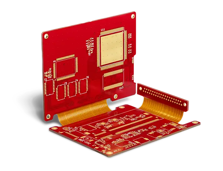
Rigid-flex boards consist of a rigid substrate and a flexible substrate laminated together and are suitable for applications requiring both rigid and flexible characteristics. If components are mounted on both sides of the printed circuit board, a rigid-flex board is an ideal choice. However, if all components are located on one side, it is more cost-effective to choose a double-sided flexible board and laminate a layer of FR4 reinforcement material onto the back.
3.5 Flexible Circuits with Hybrid Structures
Hybrid-structure flexible circuits consist of conductive layers made of different metals; typically, FR-4 is used as the dielectric material for the inner layers, while polyimide is used for the outer layers. This structure is suitable for low-temperature environments with stringent requirements for electrical signal conversion and heat transfer, and it is the only solution that meets these needs.
| Type | Structural Features | Typical Number of Floors | Minimum bend radius | Relative Cost | Typical Applications |
|---|---|---|---|---|---|
| Single-sided flexible board | Single-layer conductor + protective film | 1 | 6× plate thickness | 1.0× | Printhead Connection, Simple Jumper Wires |
| Double-Sided Flexible Circuit Board | Bilateral Conductors + Metallized Holes | 2 | 10× plate thickness | 1.6–2.2× | Camera modules, display flex cables |
| Multilayer Flexible Circuit Board | Multilayer Laminate + Plated-Through Holes | 4–10 | 20× Plate Thickness | 3–6× | Foldable-screen main flex cables, medical catheters |
| Rigid-Flex Board | Rigid and flexible sections bonded together into a single unit | 4–12 (including rigid) | Bend Zone: 20× plate thickness | 4–8× | Automotive Modules, Aerospace |
| Mixed Structure | FR-4 inner layers + PI outer layer | 4–8 | View Local Structure | 5–10× | High-Frequency/High-Thermal-Conductivity Mixed-Signal |
4. How to Quantify Flexibility: It’s Not Enough to Simply ”Be Able to Bend”
“Good flexibility” has no meaning in procurement terminology; it must be quantified in engineering terms. The bendability of an FPC is defined by three parameters:
- Minimum Bending Radius R: For static bending, R is generally required to be ≥ 6× the plate thickness; for dynamic repeated bending, R is required to be ≥ 20–40× the plate thickness (based on the total thickness of the bend area).
- Number of bends: IPC-2223 and IPC-TM-650 specify the test conditions. The single-cycle bend life ranges from several hundred cycles (for single-use installations) to over 200,000 cycles (for the hinge area of foldable screens).
- Bend Types: Single-axis bending (U-shape), folding (180°), and twisting (3D bending) place entirely different demands on copper foil; rolled copper must be used for twisting applications.
There are three material variables that determine bend life:Types of Copper Foil(Rolled copper has far better ductility than electrolytic copper, but its service life in dynamic bending applications is 3–5 times shorter),Copper Thickness(The thinner, the better; 18 μm is better than 35 μm),Adhesive Layer Thickness and Modulus(The thicker the adhesive layer, the greater the displacement of the neutral layer during bending, and the greater the strain on the copper foil.)
A Commonly Overlooked Design Flaw:Place vias, pads, and components in the bend zone. Do not place any vias or pads in the bend area; trace routing must be perpendicular to the bend axis, and traces must not overlap across multiple layers at the same location (as this would significantly increase local thickness and stress). For more detailed information on impedance and routing considerations, please refer to5 Factors Affecting FPC Impedance。
5. Comparison of Material Systems and Costs
The cost difference in FPCs stems primarily from the substrate. Below is a side-by-side comparison of common substrate options:
| Substrate Solutions | Temperature resistance | Dimensional Stability | Capable of processing fine lines | Relative Unit Price | Applicable |
|---|---|---|---|---|---|
| PET + Adhesive (3 L) | ≤105 °C | 差 | ≥150 μm | 0.5× | Low-cost components, single-use bending |
| PI + Resin (3L-FCCL) | 150–180 °C | 中 | ≥75 μm | 1.0× | Mainstream FPC, Cost-Effective Solution |
| PI, Adhesive-Free (2L-FCCL) | 200 °C+ | 优 | ≥50 μm | 1.3–1.6× | Fine-pitch traces, multiple return paths, high reliability |
| Modified PI (low Dk/Df) | 200 °C+ | 优 | ≥40 μm | 2.5–4× | High-Frequency FPC, 5G Antenna Feedlines |
| LCP (Liquid Crystal Polymer) | 280 °C+ | 优 | ≥30 μm | 5–10× | Millimeter-wave, extremely low moisture absorption scenarios |
The choice of copper foil also affects both cost and performance:Rolled Copper (RA)The grains are elongated in the rolling direction, resulting in high bending fatigue life; however, the surface roughness is low, and additional treatment is required to ensure adequate adhesion to PI. The price is 20–40% higher than that of electrolytic copper;Electrolytic Copper (ED)Low cost and good bonding strength, but short flex life. The selection criteria are simple:Whenever dynamic bending is involved, rolled copper must be used., Cost-effective one-time static installation bends can be made using electrolytic copper.
6. Cost-Effectiveness: When Is an FPC More Cost-Effective Than a Rigid Board?
In terms of unit price alone, FPCs are always 2–6 times more expensive than rigid boards. However, cost calculations must be considered at the finished product level; FPCs can reduce overall costs in four scenarios:
- Eliminate connectors and wiring harnesses: A single FPC replaces ”two rigid boards + a set of board-to-board connectors + a wiring harness,” reducing both the BOM and assembly labor hours—this is the most common source of cost savings.
- Spatial Benefits of 3D Wiring: In products with extremely limited space—such as foldable screens, TWS earbuds, and endoscopes—FPC is often the only viable solution; in such cases, the discussion of ”cost-effectiveness” refers to feasibility rather than unit price.
- Weight Loss: In aerospace and UAV applications, FPCs are 60–75% lighter than rigid boards plus wire harnesses, and the system-level benefits resulting from this weight reduction far outweigh the price difference between the two board types.
- Improve Reliability: Reducing the number of connection points means reducing the number of potential failure points. In automotive and medical applications, the reduction in failure costs typically offsets the premium associated with FPCs.
Conversely, if it’s just ”a small board with no need for bending and plenty of space,” then using an FPC would be a complete waste.There is only one criterion: whether this board needs to withstand bending during the product's lifecycle, or whether it replaces a connector or wiring harness.When the answer to both questions is "no," a rigid board is more cost-effective. For a comprehensive overview of the application advantages of FPCs, please refer toGuide to the Advantages of FPC Applications。
7. Cost Breakdown: Where the Money Goes
The breakdown of FPC quotes differs significantly from that of rigid boards. Below are the typical proportions:
- Substrate and Cover Film (35–50%): Its proportion is significantly higher than that of rigid boards, which is the fundamental reason why FPCs are expensive. PI film and two-layer FCCL are the two biggest variables.
- Reinforcement and Additives (8–15%): FR-4 reinforcement, steel sheet reinforcement, conductive adhesive, shielding film (EMI film), and adhesive backing are often omitted from calculations.
- Processing Difficulty (10–20%): Fine lines, small holes, multi-layer lamination, selective gold plating, and laser-cut contours.
- Molds and Jigs (5–12%, Disposable): Laser cutting, punching dies, SMT carriers. Flexible boards require carriers to pass through the reflow process, whereas rigid boards do not incur this cost.
- Yield Loss (5–15%): Flexible materials are difficult to process automatically; misalignment, creases, and dents are the main causes of scrap.
- Test (5–10%): Flying-probe testing, random bending life testing, and impedance testing.
Among themSMT CarrierThis is the item most likely to be overlooked during the quoting phase. Unlike rigid boards, FPCs cannot pass directly through the tracks; they must be supported by custom carrier plates (jigs). A set of these carriers costs anywhere from several thousand to tens of thousands, and they must be remade whenever the design is revised.

8. Manufacturing Challenges and Yield Killers
The manufacturing challenges of FPCs differ from those of rigid boards and primarily arise in the following areas:
| Process Steps | Main Challenges | Common Defects | Control Measures |
|---|---|---|---|
| Cutting and Handling | The sheet material is soft and prone to creasing. | Creases, dents, scratches | Vehicles for the Entire Route, Stacking Height Limits |
| Drilled Holes/Laser-Cut Holes | Contamination of PI material, resin residue on the inner walls of the holes | Rough hole walls, voids in the copper plating | Plasma Removal of Resin Residue + Parameter Optimization |
| Circuit Etching | Fine traces are prone to side-etching and open circuits. | Line width is too narrow; there is a gap | Reducing copper thickness and controlling the etching factor |
| Alignment of the Cover Film | Window Offset | Insufficient copper exposure on the pad or misalignment of the coating | Switch to a photosensitive overprint film (PI ink) |
| Laminating | Multi-layer Alignment and Interlayer Slip | Layer misalignment, air bubbles, delamination | Staged Heating, Vacuum Pressing |
| External Shaping | Laser-Cut Carbonization / Punching Burrs | Edge carbonization, dimensional out-of-tolerance | Laser Parameter Window Control + Secondary Cleaning |
The shipping inspection process also includes criteria specific to FPCs, which should be clearly specified in the specifications during the procurement acceptance process:
- Creases and Bruises: White marks (caused by stress on the substrate) in the bend area are always deemed non-conforming; in non-bend areas, the determination is based on the affected area and subject to mutual agreement.
- Cover Film Offset: The offset of the window center relative to the pad center; generally, this must be ≤0.10 mm.
- Copper Exposure and Oxidation: The surface of the pad must be free of adhesive residue from the cover film and must not show any signs of oxidation or discoloration.
- Dimensions: The dimensional tolerance for laser cutting is typically ±0.10 mm, and for punching, ±0.15 mm.
- Random Sampling for Flex Life Testing: Random sampling by batch; test conditions (radius, angle, frequency) must be specified in the specifications.
- Reinforcement Laminating: Position accuracy and bubbles; if the bubble area exceeds 5% of the reinforcement area, the part is typically rejected.
9. Product Selection Decision-Making Process
Summarize the preceding content into a six-step decision-making process:
- ConfirmBend Types and Number of Bends(Static installation / Dynamic bending / Folding); the type of copper foil and the bending radius are determined based on this.
- ConfirmMinimum Line Width and Spacing...Based on this, determine whether to use 3L or 2L substrate.
- ConfirmAre there any impedance or high-frequency requirements?,有则进入低 Dk 改性 PI 或 LCP 路线。
- Confirm是否需要集成刚性区(有元件、有连接器),决定是刚柔结合还是纯柔性 + 补强。
- Accounting整机层面的连接点数与装配工时,判断 FPC 是否真的降本。
- ConfirmSMT 载具与测试方案,把一次性投入计入报价。
10. Conclusion
FPC柔性线路板的三大主要特性,包括挠曲性和可靠性、经济性以及成本,决定了其在电子领域中的应用范围和优势。选择使用FPC柔性线路板还是传统刚性电路板取决于具体应用的需求和预算。随着技术的不断进步,FPC柔性线路板将在越来越多的领域中发挥其独特的作用。
Frequently Asked Questions
1. FPC柔性线路板适用于哪些应用?
FPC柔性线路板适用于需要灵活性、挠曲性和特殊空间要求的应用,如移动设备、医疗设备和汽车电子。
2. FPC柔性线路板和刚性电路板有何区别?
FPC柔性线路板可以自由弯曲和折叠,适应不规则形状,而刚性电路板不能。FPC柔性线路板适用于空间有限的应用。
3. 为什么FPC柔性线路板的材料成本较高?
FPC柔性线路板的材料成本高是因为它需要特殊的挠性材料,这些材料在制造和加工过程中更具挑战性。
4. FPC柔性线路板在哪些领域有广泛应用?
FPC柔性线路板广泛应用于移动设备、医疗设备、航空航天和汽车电子等领域,以满足复杂的设计需求。
5. FPC柔性线路板的未来发展趋势是什么?
FPC柔性线路板将继续发展,应用范围将扩大到更多的领域,同时材料和制造工艺也将不断改进,以降低成本并提高性能。
6. 动态弯折和静态弯折对设计有什么不同要求?
静态弯折(一次性安装弯折)最小弯折半径可取 6×板厚,电解铜即可满足;动态弯折(反复弯折)要求半径 20–40×板厚,必须使用压延铜,铜厚尽量选 18 μm 或更薄,且弯折区不得布置过孔、焊盘与元件。
7. 三层法(3L)和二层法(2L)FCCL 该怎么选?
3L-FCCL 有胶层,成本低、工艺成熟,适合线宽 ≥75 μm 的一般应用;2L-FCCL 无胶层,厚度更薄、耐温更高、尺寸稳定性更好,适合细线路(<75 μm)、多次回流焊和高可靠性场景,价格高出 30–60%。
8. 为什么 FPC 过 SMT 需要专门载具?
因为 FPC 本身柔软,无法像刚性板那样在轨道上传输和平整支撑,必须定制载板(治具)把 FPC 张紧固定后才能印刷锡膏和过回流焊。载具是一次性投入,改版就要重做,报价阶段容易被漏算。
9. 弯折区设计有哪些硬性禁止项?
禁止在弯折区布置过孔、焊盘、元件与覆盖膜拼接缝;走线方向必须垂直于弯折轴;多层走线不得在弯折区同一位置重叠;弯折区两侧应做圆弧过渡而非直角。违反这四条中的任何一条,弯折寿命通常会下降一个数量级。
10. FPC 比刚性板贵,怎么判断值不值?
看两块:一是 FPC 是否替代了连接器与线束(省下的 BOM 加装配工时往往超过板材差价);二是是否有失效成本下降(车载、医疗场景的返修与召回成本远高于板材溢价)。如果两者都不成立,且无弯折需求,刚性板更经济。
Related Reading:The Three Main Factors Causing PCB Soldering Defects · A Detailed Explanation of the Surface Plating Process for FPC Flexible Printed Circuit Boards
